Waveguide-type optical interferometer
a waveguide-type, optical interferometer technology, applied in the direction of optical waveguide light guide, optical elements, instruments, etc., can solve the problem of interferometer polarization dependence, inability to completely eliminate the polarization dependence of half-wave plate, and inability to enable interferometer to be polarization-independent, etc. problem, to achieve the effect of eliminating the polarization dependence, simple configuration and excellent mass production of optical circuits
- Summary
- Abstract
- Description
- Claims
- Application Information
AI Technical Summary
Benefits of technology
Problems solved by technology
Method used
Image
Examples
first embodiment
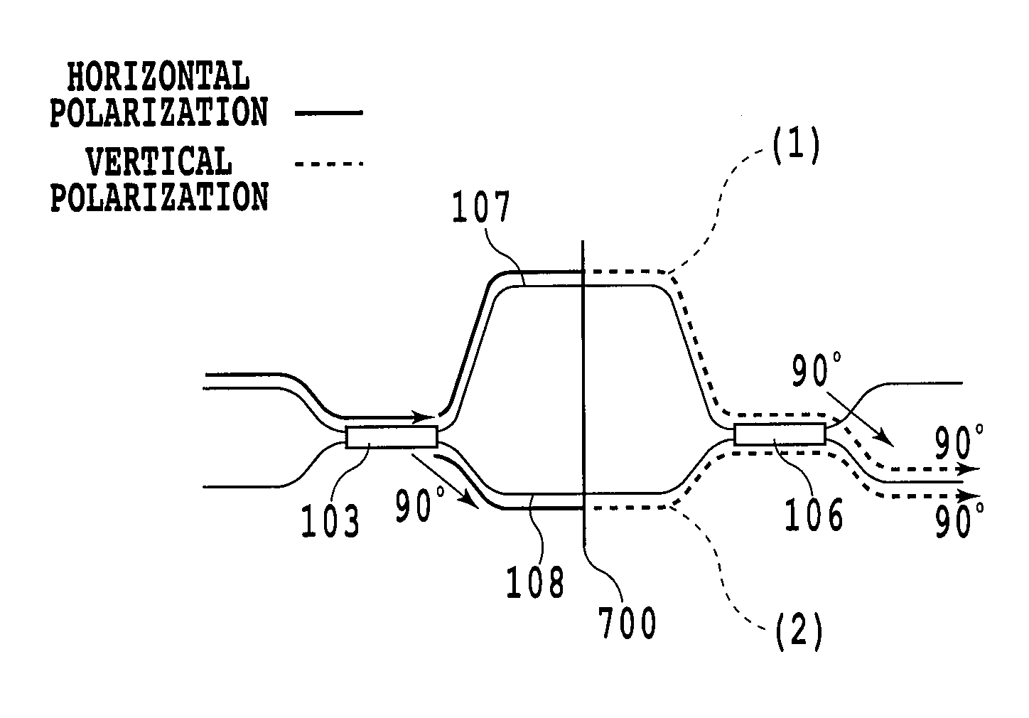
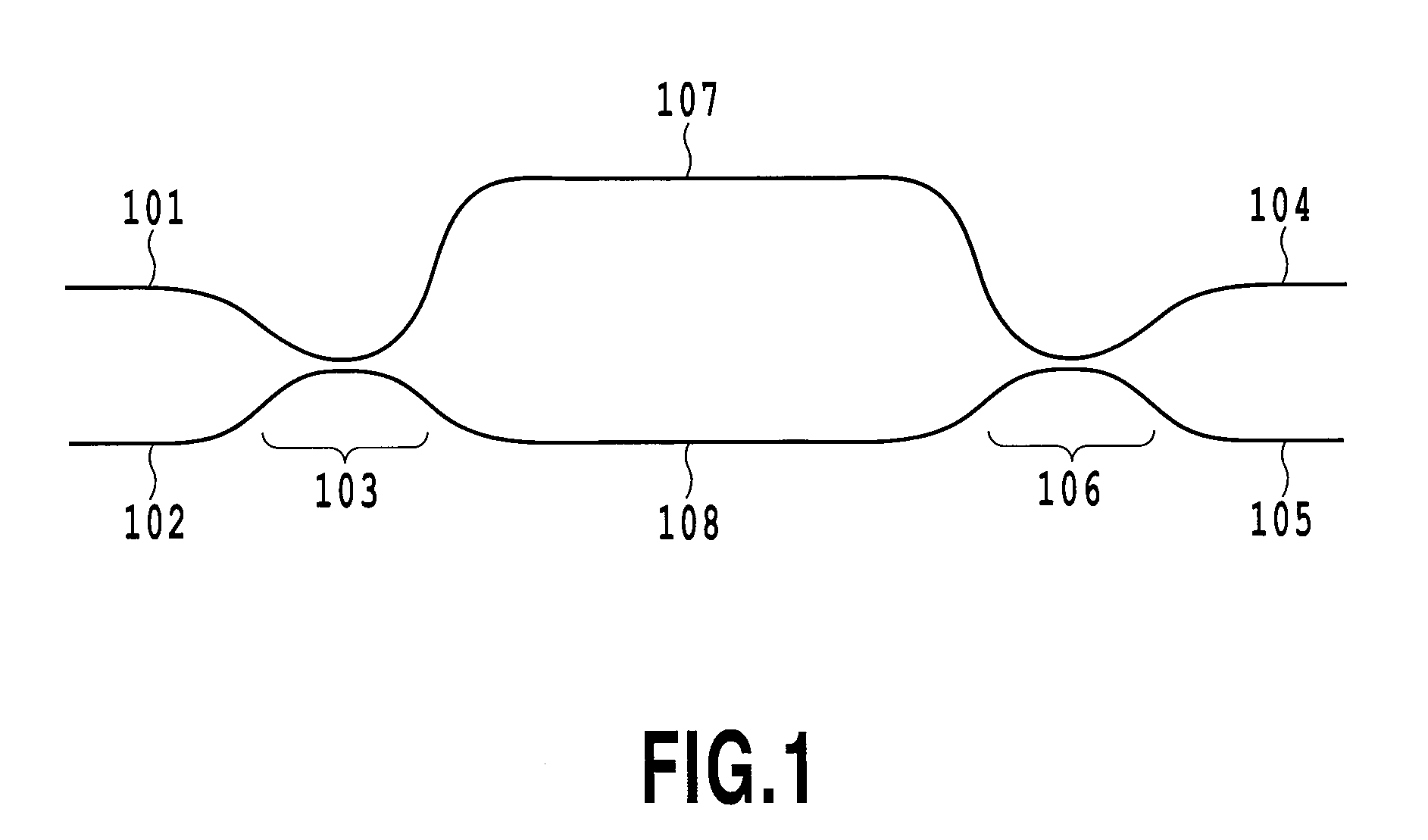
[0103]FIG. 9 is a diagram showing a waveguide-type optical interferometer according to the first embodiment of the present invention. An asymmetric MZI is configured by including an optical splitter 103 and an optical combiner 106 having a splitting ratio of 50%, and the two arm waveguides 107 and 108 of different lengths that provide a connection between the optical splitter 103 and the optical combiner 106. The long arm waveguide 107 and the short arm waveguide 108 are each formed of a multimode interference waveguide (MMI) and are birefringent. In the asymmetric MZI, a length between the two arm waveguides is adjusted so that FSR is 21 GHz. In the first embodiment, the polarization rotator is configured of a combination of two half-wave plates, that is, a first half-wave plate whose optic axis is inclined at 45° relative to the optic axes of the waveguides, and a second half-wave plate whose optic axis is parallel to the optic axes of the waveguides. Hereinafter, in order to dist...
second embodiment
[0116]FIG. 12 is a conceptual illustration showing the configuration of a polarization rotator according to the second embodiment, which implements the waveguide-type optical interferometer of the present invention. A different method from the first embodiment is used for the configuration in which the polarization rotator is implemented. The second embodiment is characterized in that a waveguide 121 having birefringence is placed on one side of a half-wave plate 122 thereby to operate the polarization rotator. Specifically, the waveguide may be designed so that the waveguide 121 in itself having the birefringence performs the function of providing the phase difference between vertical and horizontal polarizations, as in the case of the retarder described with reference to the first embodiment. The waveguide 121 corresponding to the retarder is configured in the interferometer, and thereby, the elimination of the polarization dependence of the interferometer can be achieved by the p...
third embodiment
[0139]As has been described in detail, the elimination of the polarization dependence of the interferometer caused by the light induced by polarization coupling produced in the directional coupler can be achieved by placing the polarization rotator in the optical path in the interferometer. However, it is demanded that the interferometer become polarization-independent over a wider range of wavelengths, depending on the field of application of the interferometer. In such a case, it is required that the interferometer be designed further allowing for the occurrence of interference in the arm waveguide.
[0140]The polarization rotator interposed in the interferometer effects any one of 90° rotation and −90° rotation of all polarizations propagating through the optical path. However, the polarization rotator has an optimum range of operating wavelengths, and thus, a wide range of wavelengths renders it difficult to perform accurate rotation operation for all wavelengths. Even if a match ...
PUM
 Abstract
Description
Claims
Application Information
 - R&D
- Intellectual Property
- Life Sciences
- Materials
- Tech Scout
- Unparalleled Data Quality
- Higher Quality Content
- 60% Fewer Hallucinations
Browse by: Latest US Patents, China's latest patents, Technical Efficacy Thesaurus, Application Domain, Technology Topic, Popular Technical Reports.
© 2025 PatSnap. All rights reserved.Legal|Privacy policy|Modern Slavery Act Transparency Statement|Sitemap|About US| Contact US: help@patsnap.com


