Device for increasing extinction ratio

A technology of extinction ratio and optical axis, applied in the coupling of optical waveguide, optical fiber transmission, electromagnetic wave transmission system, etc., can solve the problems of large insertion loss and inconsistent transmission coefficient

Active Publication Date: 2017-09-05
HUAWEI TECH CO LTD
View PDF4 Cites 0 Cited by
  • Summary
  • Abstract
  • Description
  • Claims
  • Application Information

AI Technical Summary

Problems solved by technology

[0004] However, in the solutions of the prior art, the polarization dependence of the 45° optical filter causes the transmission coefficients of the high-speed optical signal to be inconsistent in the S and P directions after passing through the 45° optical filter, and a large interpolation factor is introduced. damage

Method used


Image

  • Device for increasing extinction ratio
  • Device for increasing extinction ratio
  • Device for increasing extinction ratio

Examples


Embodiment Construction

[0024] In order to make the purpose, technical solutions and advantages of the embodiments of the present invention clearer, the technical solutions in the embodiments of the present invention will be clearly and completely described below in conjunction with the drawings in the embodiments of the present invention. Obviously, the described embodiments It is a part of embodiments of the present invention, but not all embodiments. Based on the embodiments of the present invention, all other embodiments obtained by persons of ordinary skill in the art without creative efforts fall within the protection scope of the present invention.

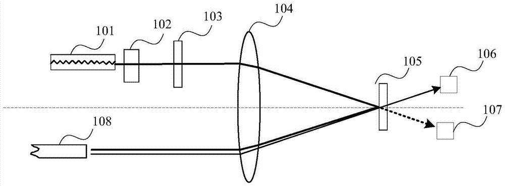
[0025] figure 2 It is a schematic structural diagram of the device for increasing the extinction ratio of the present invention. Such as figure 2 As shown, the device for improving the extinction ratio provided by this embodiment includes a DML101, an isolator 102, and an optical fiber 108, and also includes a first filter 103, a lens 104, a s...


PUM


Abstract

The invention provides a device for improving the extinction ratio, which includes a DML, an isolator and an optical fiber. The device also includes a first filter, a lens, a second filter and a photodiode assembly arranged in sequence; the isolator is arranged between the DML and the first Between the filters; the lens is arranged between the optical fiber and the second filter; wherein, the first filter is used to increase the extinction ratio of the optical signal output by the DML; the lens is used to form an angle between the optical signal and the central optical axis of the lens, The second filter is used to reflect the optical signal to the optical fiber for transmission; the second filter is used to split the optical signal up and down; the photodiode assembly includes a first photodiode and a second photodiode; wherein: the first photodiode is used The state of the downlink optical signal is detected and fed back to the DML; the second photodiode is used for photoelectric conversion of the uplink optical signal. Therefore, the insertion loss and polarization dependence in the optical path are reduced while the extinction ratio is increased.

Description

technical field [0001] Embodiments of the present invention relate to optical fiber communication technology, and in particular to a device for increasing extinction ratio. Background technique [0002] In an optical communication network, data is sent and received by an optical transmitter and an optical receiver. The extinction ratio can directly affect the sensitivity of the optical receiver. In order to increase the extinction ratio, a Directly Modulated Laser (DML) is usually used to increase the amplitude of the modulation signal to increase the extinction ratio, but the use of DML will cause a large chirp. As a result, the dispersion becomes larger and the signal quality deteriorates. [0003] In the prior art, the solution to the chirp problem is to use DML in combination with a multi-cavity filter, such as figure 1 As shown, an isolator, a 45° filter and a multi-cavity filter are arranged in sequence in front of the optical path. The 45° filter can realize uplink ...

Claims


Application Information

Patent Timeline
Patent Type & Authority Patents(China)
IPC IPC(8): H04B10/25H04B10/075G02B6/26
Inventor 温运生
Owner HUAWEI TECH CO LTD
Why Eureka
Try Eureka