Micro-ring resonant cavity electro-optical modulator based on graphene/molybdenum disulfide heterojunction

A technology of microring resonator and electro-optical modulator, which is applied in the field of optoelectronics, can solve the problems of low extinction ratio, poor modulation depth, and environmental temperature sensitivity, and achieve high extinction ratio, small insertion loss, and good modulation depth.

Inactive Publication Date: 2016-03-02
UNIV OF ELECTRONICS SCI & TECH OF CHINA
View PDF5 Cites 24 Cited by
  • Summary
  • Abstract
  • Description
  • Claims
  • Application Information

AI Technical Summary

Problems solved by technology

[0006] The invention overcomes the deficiencies of the prior art and provides a microring resonant cavity electro-optic modulator based on graphene / molybdenum disulfide heterojunction, which solves the problem that the electro-optic modulator is relatively sensitive to the ambient temperature in the past, and the existing graphene Technical problems of poor modulation depth and low extinction ratio of optical modulators

Method used


Image

  • Micro-ring resonant cavity electro-optical modulator based on graphene/molybdenum disulfide heterojunction
  • Micro-ring resonant cavity electro-optical modulator based on graphene/molybdenum disulfide heterojunction
  • Micro-ring resonant cavity electro-optical modulator based on graphene/molybdenum disulfide heterojunction

Examples


Embodiment

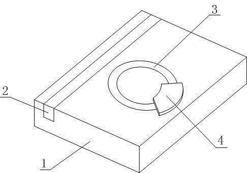
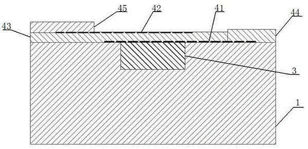
[0027] Such as figure 1 , figure 2 As shown, the microring resonator electro-optic modulator based on the graphene / molybdenum disulfide heterojunction includes a base layer 1, a straight light waveguide 2, a microring resonator waveguide 3 and a graphene cover layer 4, a straight light waveguide 2 and The microring resonator waveguide 3 is embedded in the base layer 1, and a coupling distance is left between the straight light waveguide 2 and the microring resonator waveguide 3, and the graphene covering layer 4 partially covers the microring resonator waveguide 3 Surface; the graphene cover layer 4 includes a first graphene layer 41, a second graphene layer 42, molybdenum disulfide 43, a first electrode 44 and a second electrode 45, the first graphene layer 41 and the second graphene layer The layers 42 are isolated by molybdenum disulfide 43, the first graphene layer 41 extends outward from the microring resonator waveguide 3 side and connects to the first electrode 44, an...

specific Embodiment approach

[0035] In this embodiment, a light wave with a wavelength of 1.55 μm is used, the material of the base layer 1 is silicon dioxide, the material of the straight light waveguide 2 and the microring resonator waveguide 3 is silicon nitride, and the width and thickness of the straight light waveguide 2 are 1 μm and 0.3 μm respectively. μm, the coupling pitch is 0.5 μm, the outer radius of the microring resonator waveguide 3 is 40 μm; the material of the first electrode 44 and the second electrode 45 is gold.

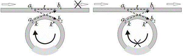
[0036] image 3It is a schematic diagram of the working principle of the electro-optic modulator in this embodiment, and the applied voltage can dynamically tune the absorption coefficient of graphene to light, thereby controlling the optical loss of the microring resonator waveguide 3; when the optical loss of the microring resonator waveguide 3 is very small, The light is coupled into the microring resonator waveguide 3, the straight light waveguide 2 has no signal output,...


PUM


Abstract

The invention discloses a micro-ring resonant cavity electro-optical modulator based on a graphene/molybdenum disulfide heterojunction. The micro-ring resonant cavity electro-optical modulator comprises a substrate layer, a direct-light waveguide, a micro-ring resonant cavity waveguide and a graphene covering layer. The direct-light waveguide and the micro-ring resonant cavity waveguide are embedded into the substrate layer, and a coupling space is reserved between the direct-light waveguide and the micro-ring resonant cavity waveguide. The upper surface of the micro-ring resonant cavity waveguide is covered with a part of the graphene covering layer. The graphene covering layer comprises a first graphene layer, a second graphene layer, molybdenum disulfide, a first electrode and a second electrode, wherein the first graphene layer and the second graphene layer are isolated by the molybdenum disulfide, the first graphene layer stretches outwards from one side of the micro-ring resonant cavity waveguide and is connected with the first electrode, and the second graphene layer stretches outwards from the other side of the micro-ring resonant cavity waveguide and is connected with the second electrode. The micro-ring resonant cavity electro-optical modulator has extremely low optical loss, a low thermo-optical coefficient, low insertion loss, large environment temperature tolerance, a good modulation depth and a high extinction ratio.

Description

technical field [0001] The invention relates to an electro-optic modulator, which belongs to the field of optoelectronic technology, and more specifically relates to a micro-ring resonant cavity electro-optic modulator based on graphene / molybdenum disulfide heterojunction. Background technique [0002] The optical modulator is the basis and key component of the optical communication system. Its function is to change the intensity, phase, polarization and other characteristics of the optical carrier passing through the optical modulator, and load the electrical signal on the optical carrier. Traditional optical modulators are mostly based on electro-optic, thermo-optic or silicon carrier-based dispersion effects of lithium niobate materials, and generally have large device volumes. [0003] The advent of graphene has aroused a worldwide research upsurge, it is the thinnest, strongest and most stable structure among known materials. As a two-dimensional monolayer of carbon at...

Claims


Application Information

Patent Timeline
Patent Type & Authority Applications(China)
IPC IPC(8): G02F1/035
CPCG02F1/035
Inventor 陆荣国叶胜威田朝辉夏瑞杰寿晓峰刘永
Owner UNIV OF ELECTRONICS SCI & TECH OF CHINA
Why Eureka
Try Eureka