Polarized light assembly with double metallic layer grating and manufacturing method thereof

A technology of bimetallic layer and manufacturing method, applied in the direction of polarizing element, etc., can solve the problems of incomplete compliance, great variation of the extinction ratio of polarizing components, and inability of high extinction ratio of polarizing components.

Active Publication Date: 2005-06-22
IND TECH RES INST
View PDF5 Cites 25 Cited by
  • Summary
  • Abstract
  • Description
  • Claims
  • Application Information

AI Technical Summary

Problems solved by technology

However, the extinction ratio of the polarizing component of this method varies greatly, for example, the extinction ratio at 550nm wavelength is only 20:1
[0009] Since the extinction ratio of polarizing components currently used in the visible spectrum can only be guaranteed to be greater than 100, this cannot fully meet the requirements for optical devices that require ultra-high extinction ratios (greater than 1000).
Moreover, when applied to an optical device with a large incident light angle (such as a liquid crystal display with a light source installed on the side), the known polarizer cannot provide a high extinction ratio at any incident angle.

Method used


Image

  • Polarized light assembly with double metallic layer grating and manufacturing method thereof
  • Polarized light assembly with double metallic layer grating and manufacturing method thereof
  • Polarized light assembly with double metallic layer grating and manufacturing method thereof

Examples


experiment example 1

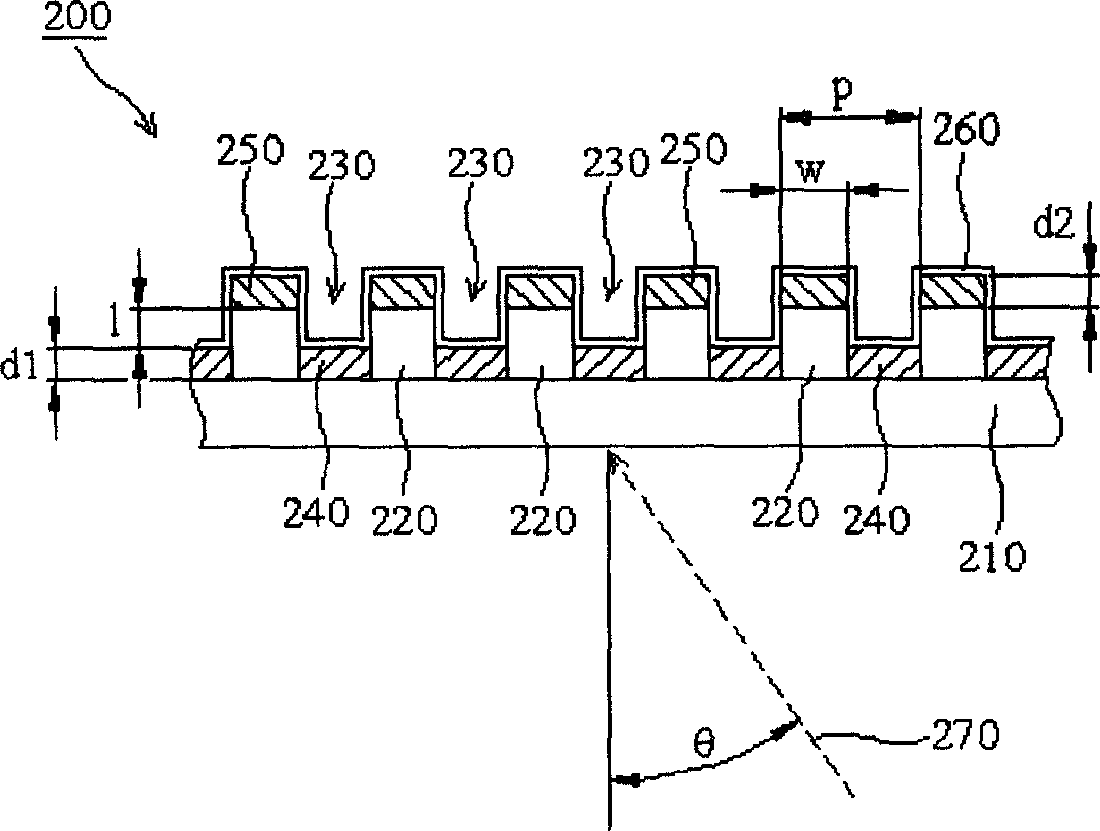
[0075] see figure 2In the polarizing component 200 of the present invention, the wavelength of the incident light 270 is 400-700nm (ie visible spectrum), the metal layers 240 and 250 are made of aluminum, the dielectric layer 220 is made of PMMA, and the substrate 210 is made of glass. The size conditions of each layer are: the thickness of the substrate 210 is 1000 μm, d1=d2=70nm, l=30nm, p=100nm, w=50nm and θ=0°. The reflectivity R of TE light under this condition TE and penetration rate T TE The relationship between the wavelength of visible light and the wavelength of visible light is as follows Figure 6A shown, while the reflectance R of TM light TM and penetration rate T TM The relationship between the wavelength of visible light and the wavelength of visible light is as follows Figure 6B shown.

[0076] Depend on Figure 6A and Figure 6B It can be seen that the transmittance T of TM light TM Most of them are above 70%, and the transmittance of TE light T T...

experiment example 2

[0078] see figure 2 The polarizing assembly 200 of the present invention. The experimental conditions are set as follows: the wavelength λ of the incident light 270 is 470nm, 550nm, 610nm, the metal layers 240 and 250 are aluminum, the dielectric layer 220 is PMMA, the substrate 210 is glass, the thickness of the substrate 210 is 1000 μm, d1=d2=70nm, l=30nm, p=100nm, w=50nm and θ=0°, 45°, 80°. The incident angle θ and extinction ratio T under this condition TM / T TE The experimental results are shown in Table 1:

[0079] Table 1

[0080]

[0081] It can be seen from Table 1 that the polarizing component of the present invention still has a relatively high extinction ratio (greater than 1000) when the incident light is at a large incident angle (80°).

experiment example 3

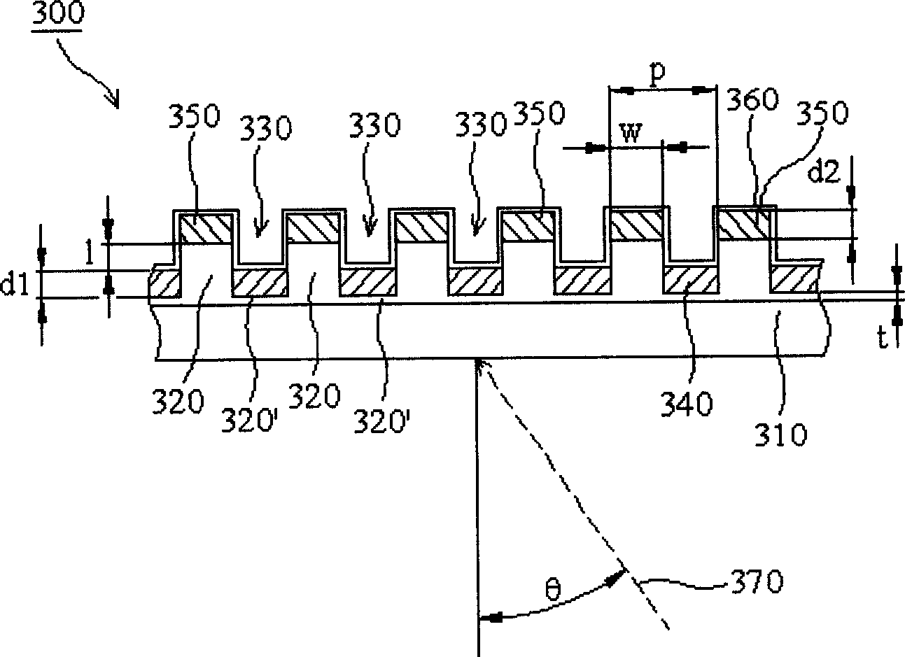
[0083] see figure 2 In the polarizing component 200 of the present invention, the wavelength of the incident light 270 is 400-700nm (ie visible spectrum), the metal layers 240 and 250 are gold, the dielectric layer 220 is PMMA, and the substrate 210 is glass. The size conditions of each layer are: the thickness of the substrate 210 is 1000 μm, d1=d2=70nm, l=30nm, p=180nm, w=90nm and θ=0°. The reflectance R of TE light under this condition TE and penetration rate T TE The relationship between the wavelength of visible light and the wavelength of visible light is as follows Figure 7A shown, while the reflectance R of TM light TM and penetration rate T TM The relationship between the wavelength of visible light and the wavelength of visible light is as follows Figure 7B shown.

[0084] Depend on Figure 7A and Figure 7B It can be seen that the transmittance T of TM light TM Most of them are above 70%, and the transmittance of TE light T TE It is almost zero (the act...


PUM

PropertyMeasurementUnit
thicknessaaaaaaaaaa
distanceaaaaaaaaaa
thicknessaaaaaaaaaa

Abstract

This invention provides a polarized component with double-metal layer gratings. Multiple parallel dielectric layers having a period are formed on a transparent base, a groove is set between adjacent dielectric layers, a first metal layer having a first thickness is formed on the groove, a second metal layer with a second thickness and a width formed on the dielectric layer, in which, a vertical distance of 10~100um is between the first and second metal layers to isolate them. The period is 10~250nm, the thickness is 30~150nm, the first is equal to the second. The proportion of width/period is 25~75%. This invention also discloses the manufacturing method.

Description

technical field [0001] The invention relates to a polarizing component with a high extinction ratio and a manufacturing method thereof, in particular to a polarizing component with a double metal layer grating suitable for the visible spectrum and a manufacturing method thereof. Background technique [0002] The use of arrays of parallel wires to polarize radio waves has been known for over a hundred years. Currently, metal grids are usually formed by arrays of thin wires on a transparent substrate for polarizing the electromagnetic spectrum. [0003] figure 1 It is a traditional single metal layer grating polarizer 100 . The wire grid polarizer includes a plurality of parallel conductive electrodes 110 formed on a dielectric substrate 120 . The main influencing factors of the polarization mechanism of the metal grid polarizer 100 are: the period P of the conductor electrode 110 , the width W of the conductor electrode 110 and the thickness D of the conductor electrode 11...

Claims


Application Information

Patent Timeline
Patent Type & Authority Applications(China)
IPC IPC(8): G02B5/30
Inventor 丘至和郭惠隆刘怡君陈品诚
Owner IND TECH RES INST
Why Eureka
Try Eureka