Organic light-emitting element and display device having the same

a technology of light-emitting elements and display devices, which is applied in the direction of organic semiconductor devices, solid-state devices, semiconductor devices, etc., can solve the problems of reducing the micro-cavity resonance effect, and achieve the effect of improving the efficiency and reducing the efficiency drop and improving the lifespan of the organic light-emitting elemen

Active Publication Date: 2018-03-01
LG DISPLAY CO LTD
View PDF4 Cites 5 Cited by
  • Summary
  • Abstract
  • Description
  • Claims
  • Application Information

AI Technical Summary

Benefits of technology

[0005]In a top-emission OLED device, light exists via the cathode, and thus the cathode is formed to be translucent or transparent. When a metal film such as aluminum (Al) is used for the cathode, the metal film is required to be thin to improve the transmittance of the cathode. And, the reflectivity of the cathode is reduced, such that the efficiency of the organic light-emitting element may be lowered. In detail, the efficiency of the organic light-emitting element can be increased by generating a micro-cavity resonance effect in the organic light-emitting element. If the reflectivity of the cathode is lowered, it may reduce the micro-cavity resonance effect.

Problems solved by technology

If the reflectivity of the cathode is lowered, it may reduce the micro-cavity resonance effect.

Method used


Image

  • Organic light-emitting element and display device having the same
  • Organic light-emitting element and display device having the same
  • Organic light-emitting element and display device having the same

Examples


first embodiment

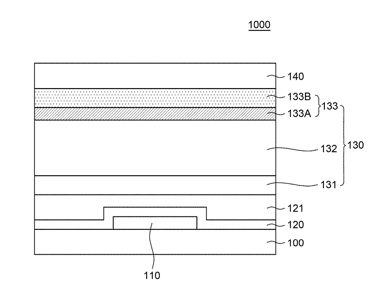
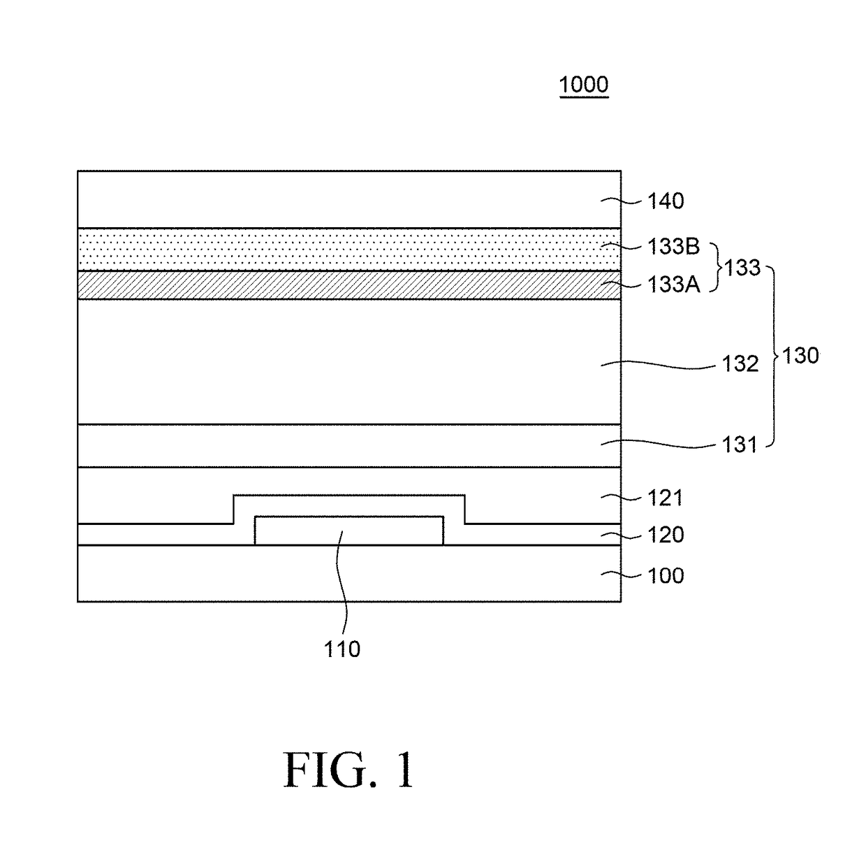
[0048]FIG. 1 is a cross-sectional view of an organic light-emitting display (OLED) device according to the present disclosure.

[0049]The OLED device 1000 includes a substrate 100, an organic light-emitting element 130 disposed on the substrate 100, and an encapsulation layer 140.

[0050]A driving circuit 110 for driving the organic light-emitting element 130 may be disposed on the substrate 100. The driving circuit 110 may include a transistor, a capacitor, etc. The driving circuit 110 may be formed in each of a plurality of sub-pixels formed on the substrate 100. The source electrode or the drain electrode of a transistor may be connected to the anode 131 of the organic light-emitting element 130 to transmit a driving signal to the organic light-emitting element 130.

[0051]The substrate 100 serves to support and protect various elements of the OLED device. The substrate 100 may be formed of an insulating material, and may be formed of, for example, glass, polyimide, acryl, polyacrylate...

second embodiment

[0085]FIG. 6 is a cross-sectional view for illustrating influence on an organic light-emitting element in an OLED device according to the present disclosure when it is exposed to UV light.

[0086]FIG. 6 illustrates a stack structure of layers from the cathode 133 to the encapsulation layer 140 among the layers of the OLED device 1000 of FIG. 1. Therefore, the redundant description will be omitted.

[0087]Referring to FIG. 6, a first cathode 133A of the cathode 133 may be disposed on a second cathode 133B. The encapsulating layer 140 may be disposed on the cathode 133, such that it is possible to reduce permeation of moisture, oxygen, etc. from the outside into the organic light-emitting element.

[0088]In addition, a capping layer 150 may be disposed between the cathode 133 and the encapsulation layer 140. The capping layer 150 may cover the cathode 133 of the organic light-emitting element to reduce oxygen and moisture introducing from the outside, and may attach the organic light emitti...


PUM


Abstract

An organic light-emitting display device has improved transmittance and UV light reliability by optimizing the thickness and material of a cathode. An organic light-emitting display device comprises an organic light-emitting element on a substrate, the organic light-emitting element including an anode, an organic light emitting layer, and a cathode, an organic layer between the substrate and the organic light-emitting element, and an auxiliary layer adjacent to the cathode and including a material having electron injection ability, such that the influence of UV lights on the OLED device is reduced, thereby improving the efficiency and lifespan of the organic light-emitting element.

Description

CROSS-REFERENCE TO RELATED APPLICATIONS[0001]This application claims the priority from Korean Patent Application No. 10-2016-0112251 filed on Aug. 31, 2016, in the Korean Intellectual Property Office, the disclosure of which is incorporated herein by reference in its entirety.BACKGROUNDTechnical Field[0002]The present disclosure relates to an organic light-emitting element with improved transmittance and UV light reliability, and an organic light-emitting display (OLED) device having the same.Description of the Related Art[0003]An OLED device includes an organic light-emitting element including an organic light emitting layer, an anode and a cathode, a driving element for driving the organic light-emitting element such as a transistor, a capacitor, etc. In detail, the OLED device utilizes the phenomenon that holes injected from an anode and electrons injected from a cathode recombine in an emission layer to form excitons, and light of a particular wavelength is generated by energy r...

Claims


Application Information

Patent Timeline
Patent Type & Authority Applications(United States)
IPC IPC(8): H01L51/50H01L51/52
CPCH01L51/5092H01L51/5228H01L51/504H01L51/5265H01L2251/558H01L51/5231H10K50/171H10K50/824H10K50/828H10K50/82H10K2102/3026Y02E10/549H10K50/852H10K50/844H10K2102/351H10K85/351H10K85/371H10K77/111H10K50/13H10K50/826
Inventor KWON, SUN KAPKIM, KWAN SOOHAN, KYU ILKIM, KWANG HYUNKIM, MI NA
Owner LG DISPLAY CO LTD
Why Eureka
Try Eureka