Composite material and method for producing a composite material

a composite material and composite material technology, applied in the field of composite materials, can solve the problems that the process step of adhesion bonding is additional time and cost-intensive, and achieve the effect of simple and cost-efficien

Inactive Publication Date: 2012-04-19
ALBERT HANDTMANN ELTEKA
View PDF0 Cites 5 Cited by
  • Summary
  • Abstract
  • Description
  • Claims
  • Application Information

AI Technical Summary

Benefits of technology

[0003]Therefore, the present invention provides a composite material having improved properties, which composite material can also be produced by means of a simple and cost-efficient method.
[0005]A composite material according to the invention comprises a metal component, such as in particular a metal foam component and preferably an aluminum foam component—such as they are for example available from suppliers as purchased parts or outsourced items as per geometric specifications—which composite material is at least partially surrounded or enclosed by, in particular completely encapsulated with, Lauramid®. As a result, there is created a highly wear-resistant and salt-water resistant composite or hybrid material having good corrosion and dry-running properties and high chemical resistance, which composite at the same time also exhibits high rigidity at low weight. Thus, the composite material according to the invention is highly suitable for use in automotive engineering and aircraft construction. The composite material according to the invention is also suitable for rail vehicles as well as for the purpose of reducing resonance effects and absorbing or diminishing shocks in many areas of mechanical engineering, as well as for shielding electromagnetic fields, the so-called EMC shielding. A special field of application of the composite material according to the invention, for example, is the use as a material for the load-bed of transporters and trailers. Lauramid® is a polyamid material of class PA 12G, which is distributed by Albert Handtmann Elteka GmbH & Co. KG.
[0006]Preferably, the metal component is designed open-pored at least at its edges, which may be achieved for example by corresponding saw cuts for separating individual metal components from a larger cast metal foam part. Consequently, the Lauramid may easily penetrate into the pores of the metal component and connect inseparably with the metal component by forming cross-linking or interlocking. This minimizes the risk that the Lauramid separates from the metal component, no adhesive being required.
[0007]It is possible to obtain a particularly wear-resistant component made from the composite material according to the invention when the metal component is completely or at least essentially completely enclosed by the Lauramid. “Essentially completely enclosed” here means that the metal component is surrounded by Lauramid except for those surfaces of the metal component which had possibly been in contact with or rested against retaining elements for supporting the metal component in a casting mold when the metal component was encapsulated with Lauramid during the casting process.
[0008]According to an advantageous further development of the invention, the metal component is designed as a flat element of relatively small thickness, which metal component comprises two main surfaces completely or at least essentially covered by Lauramid. Thus, the respective main surfaces are well-protected from wear, i.e. they exhibit favorable properties with respect to abrasion. Since the small side surfaces are not covered by Lauramid, several such elements may easily be arranged adjacent to one another and be assembled together, e.g. by means of tongue and groove joints as facade elements or the like.
[0015]The molten Lauramid is stirred prior to being poured into the mold. Stirring times of 5 to 15 minutes, in particular of about 7 to 10 minutes, and particularly preferably of about 8 to 8.5 minutes are advantageous since the Lauramid assumes then a viscosity which makes it possible to form a particularly strong connection with the aluminum foam. Stirring times of about 8 to 8.5 minutes and temperatures of about 160° C. make it even possible to completely fill the foam structure when the Lauramid is poured, so that a connection between the plastic material and the metal component results, which is practically no longer separable.

Problems solved by technology

On the one hand, a disadvantage of this is that the adhesive bonding requires an additional time and cost intensive process step in order to produce such a composite material.

Method used


Image

  • Composite material and method for producing a composite material
  • Composite material and method for producing a composite material

Examples


first embodiment

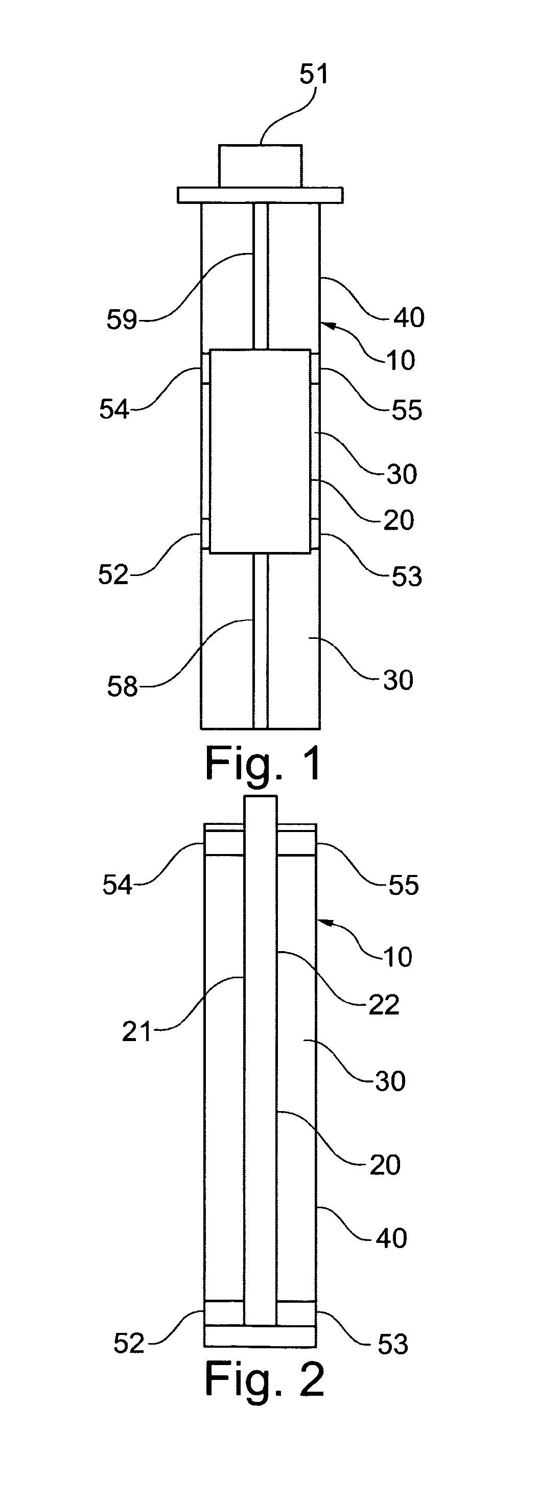
[0025]According to what is shown in FIG. 1, the composite material 10 according to the invention is produced in that an aluminum foam body 20, which represents a non-limiting example of a metal component, is arranged in a casting mold 40. By means of retaining elements 52 to 55, which may be designed as retaining plates or mandrels, the aluminum foam body 20 is fixed in the casting mold 40 so that it cannot move horizontally. Moreover, the aluminum foam body 20 is secured in the casting mold 40 against movement in the vertical direction by retaining elements 58 and 58, which may also be designed as retaining plates or mandrels. In order to efficiently prohibit the aluminum foam body 20 from floating in the casting mold 40 when the Lauramid 30 is poured, a retaining element 51 in the form of a heavy holding block exerts a force from above on the aluminum foam body 20. As can be seen from FIG. 1, the aluminum foam body 20 is completely enclosed by Lauramid 30. To put it more exactly, ...

second embodiment

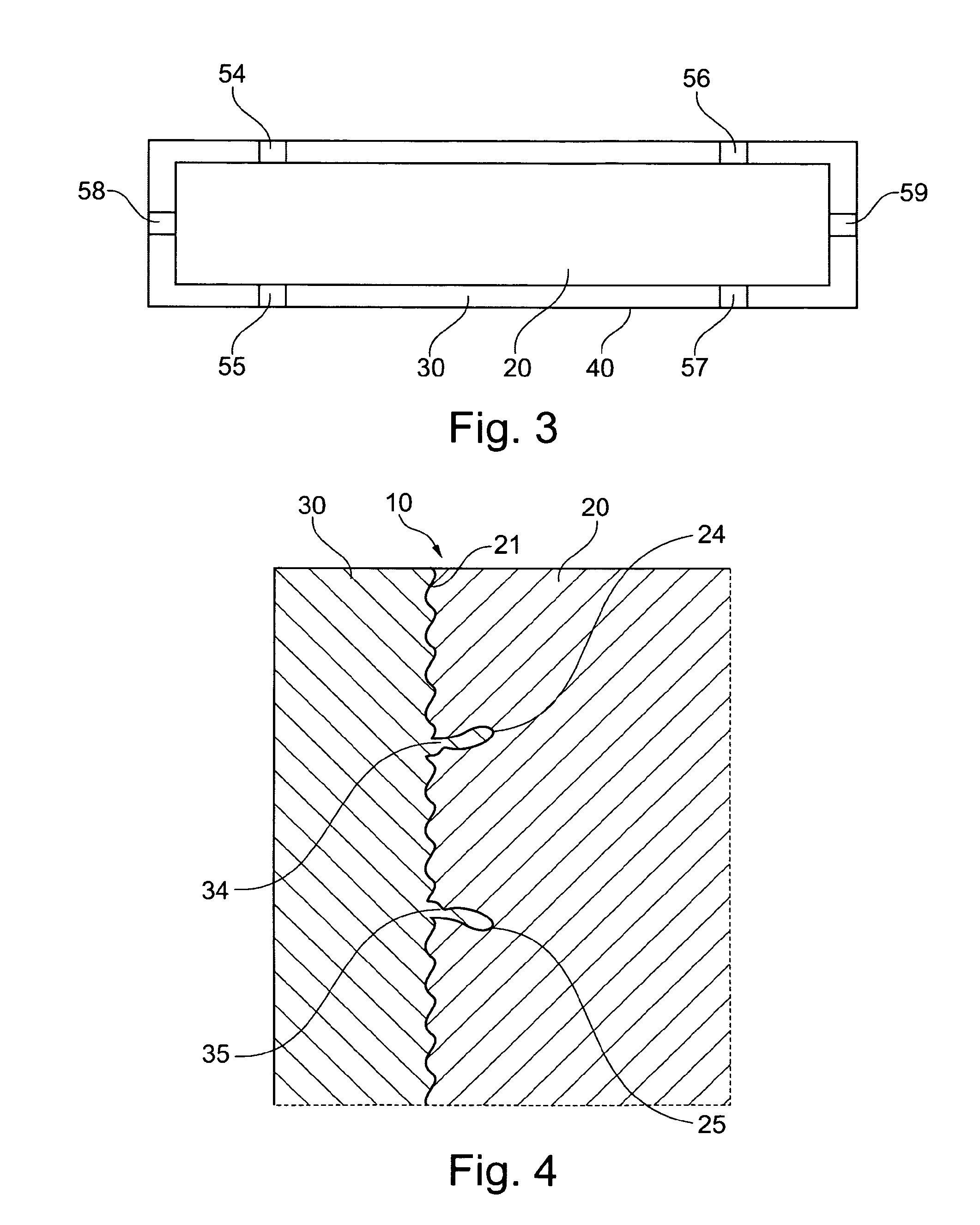
[0029]According to FIG. 2, in the composite material 10 according to the invention, the metal component is designed as a flat aluminum foam plate 20. The aluminum foam plate 20 comprises a first main surface 21 which is shown at the left of FIG. 2 and a second main surface 22 which is shown at the right, both surfaces being almost completely covered by Lauramid 30. As can be taken from FIG. 2, the end face of the aluminum foam plate 20 protruding at the top of the casting mold 40 is not covered by Lauramid, and also those sites where the retaining elements 52 to 55 rest against the aluminum foam plate 20 while the Lauramid is poured into the casting mold 40 are free from Lauramid. A retaining plate for securing the aluminum foam plate 20 against floating during the pouring process is not shown in FIG. 2 for the sake of simplicity, and anyway, does not form part of the composite material 10 according to the invention.

[0030]For producing the second embodiment of the composite material...


PUM

PropertyMeasurementUnit
thicknessaaaaaaaaaa
temperatureaaaaaaaaaa

Abstract

The invention relates to a composite material (10), comprising a metal component (20), in particular a metal foam component, preferably an aluminum foam component, and Lauramid (30) with which the metal component (20) is encapsulated, as well as to a method for producing the composite material (10) in a working step during the casting process.

Description

TECHNICAL FIELD[0001]The present invention relates to a composite material as well as to a method for producing such composite material.BRIEF DISCUSSION OF RELATED ART[0002]The number of fields in which composite materials can be used increases continuously. Moreover, there are again and again developed new composite materials in order to use them for certain purposes. For example, there are known composite materials where glass fiber or carbon fiber mats, plastics or wood veneer are adhesively bonded to a metal component, in particular an aluminum foam component. Such adhesive bonding is often done by means of an epoxy resin. On the one hand, a disadvantage of this is that the adhesive bonding requires an additional time and cost intensive process step in order to produce such a composite material. On the other hand, it is an aim to improve the properties of composite materials, in particular their wear resistance, corrosion resistance, chemical resistance, e.g. to salt water, as w...

Claims


Application Information

Patent Timeline
Patent Type & Authority Applications(United States)
IPC IPC(8): B32B1/04B32B3/26
CPCB29C37/0082B29C39/10B29C39/123B29K2077/00Y10T428/239B32B5/18B32B15/08B32B27/34B29K2705/02B32B3/06B32B27/065B32B2266/045B32B2266/06B32B2307/212B32B2307/50B32B2307/714B32B2307/718B32B2457/00B32B2605/08B32B2605/10B32B2605/18B32B7/05Y10T428/249953
Inventor VOLLMANN-SCHIPPER, JOERG
Owner ALBERT HANDTMANN ELTEKA
Why Eureka
Try Eureka