
High-tolerance broadband-optical switch in planar lightwave circuits

a technology of optical switch and high-tolerance broadband, which is applied in the direction of optics, optical light guides, instruments, etc., can solve the problems of high electrical power consumption, complicated control and production of broadband mzi optical switches

Inactive Publication Date: 2003-06-26
LYNX PHOTONIC NETWORKS
View PDF10 Cites 25 Cited by
  • Summary
  • Abstract
  • Description
  • Claims
  • Application Information

AI Technical Summary

Benefits of technology

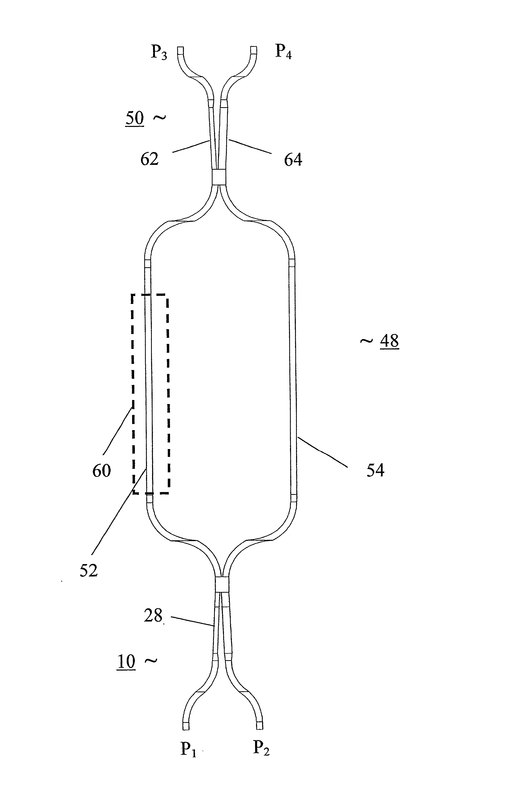
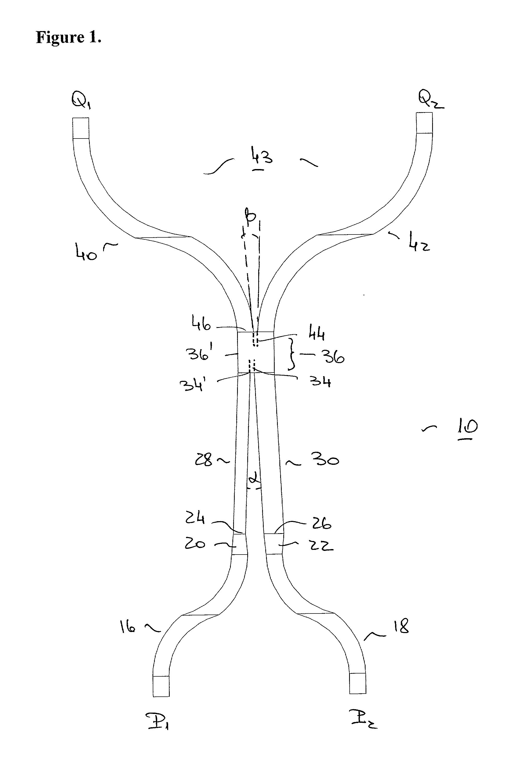
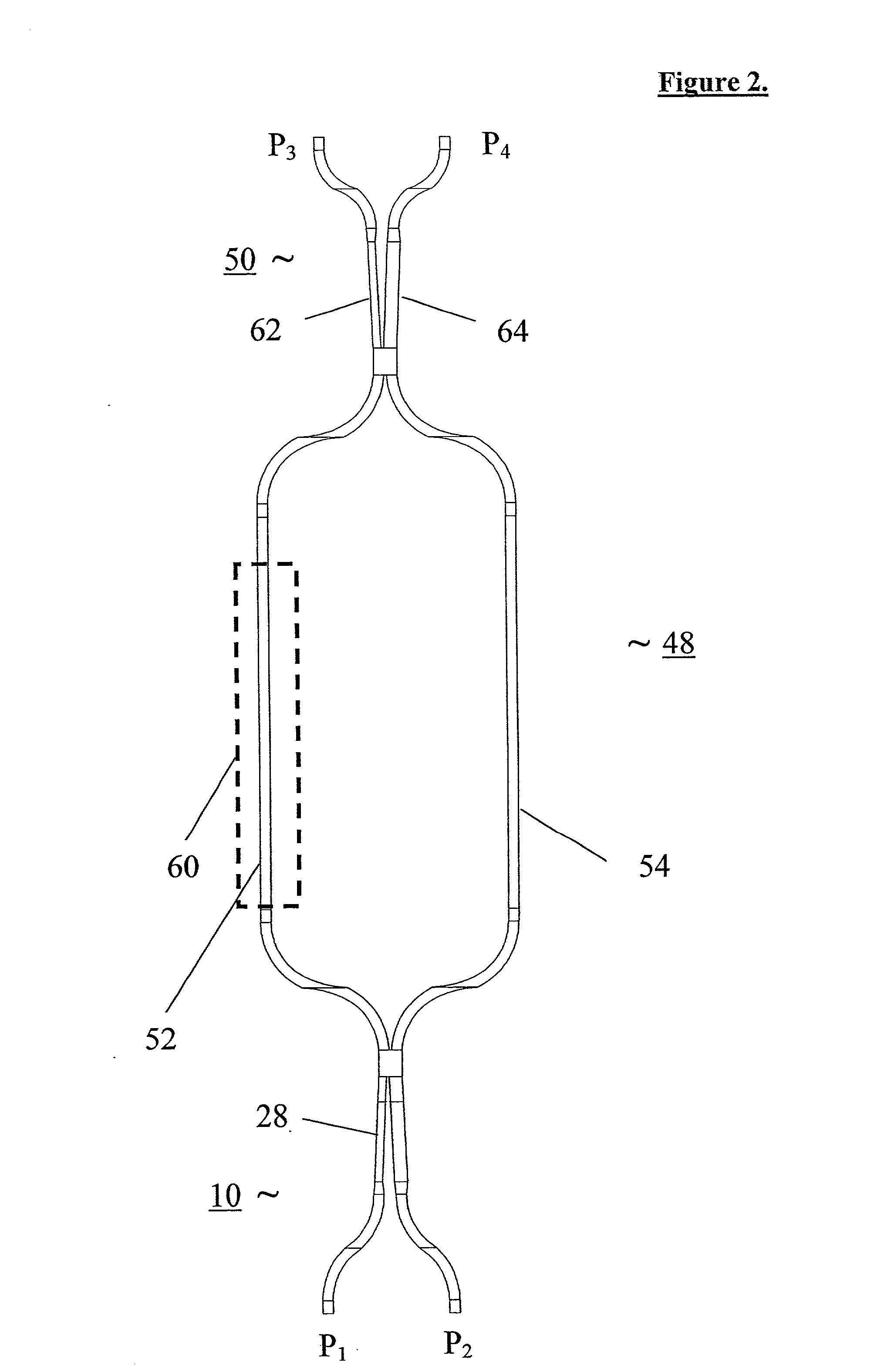
[0015] According to the present invention there is provided an optical switch having a main propagation axis, comprising a Y-splitter that includes an input waveguide and a first pair of symmetric branches, a 3 dB adiabatic coupler having a pair of second symmetric branches, the coupler further characterized by having two straight branches with different widths and separated over a coupling length by a changing spacing therebetween, the Y-splitter and the adiabatic coupler facing each other with their respective symmetric branches along the main propagation axis in a mirror image, two identical arms connecting the first and second pairs of branches optically to each other along the main propagation axis, and at least one active element coupled to at least one of the identical arms for dynamically changing an optical property of the at least one arm, whereby the implementation of the switch in a planar lightwave circuit provides a switch which is practically polarization independent, has a low loss and a very high extinction ratio over an exceptionally broad band range.

Problems solved by technology

However, a standard MZI is not broadband, due to the high wavelength dependency of its couplers, and in some configurations, also due to the length difference between its two arms.
Few attempts to produce broadband MZI optical switches were made in the past.
This device is very long and uses three electrical drivers and three active electrodes, thus having complicated control and consuming high electrical power.
In addition, its Extinction Ratio (ER) performance is insufficient--17 dB over the spectral range of 1.25-1.65 .mu.m.
These couplers and MZI switches have a few disadvantages: they must be very long in order to be adiabatic, and the coupling effect of the small (few .mu.m) gap between the coupler's waveguides is very sensitive to fabrication, e.g. to over-etch, material stresses, etc., resulting in a deteriorated extinction ratio, or alternatively in a narrowed operational wavelength window.
Under normal fabrication conditions, the ER over the spectral range of 1.25-1.6 .mu.m is only 5 dB, which is also insufficient for most current applications.
However, such couplers have a wavelength-dependent response.
However they may be generally non-identical.
Moreover, a fabrication process-induced asymmetry of the arms, or coupler related phase-difference deviation from the desired value, may result in a shift of the minimal / maximal transmission point from the passive (zero voltage) operational state.
If the active component can only increase / decrease the refractive index (e.g. a thermo-optical heater), and if only one active component is fabricated, it can only actively correct the passive state when the minimal transmission point has shifted towards the one (positive voltage) side of the transmission characteristics of that active component.
Although different wavelengths require different changes of the refractive index to achieve a .pi. phase shift, this does not spoil the broadband extinction ratio in the output port which is turned off in the passive operational state, though this may cause some loss at that port (typically 0.3-0.5 dB).

Method used


Image

  • High-tolerance broadband-optical switch in planar lightwave circuits
  • High-tolerance broadband-optical switch in planar lightwave circuits
  • High-tolerance broadband-optical switch in planar lightwave circuits

Examples


Embodiment Construction

[0042] A broadband optical switch according to the present invention was designed and fabricated in Silica (channel buried waveguides) on Silicon (substrate) with .DELTA.n=0.75% (between the core and the clad of the waveguides, the clad being also silica but with a different refractive index) utilizing the thermo-optic effect. The length of the 2.times.2 configuration (FIG. 2) was about 20 mm, whereas the length of the 1.times.2 configuration (FIG. 3) was about 15 mm. The width difference between the wide and narrow legs of the adiabatic couplers in each switch was typically about 0.4 micrometer, while the typical width of each leg was around 4 micrometer (e.g one was typically 3.8 micrometer, the other 4.2 micrometer). The actual leg width is less important than the width difference. Both devices provided similar performances, except for a better extinction ratio (ER) of the 2.times.2 configuration at the cross output. The ER results (theoretical and experimental) of the 2.times.2 ...


PUM


Abstract

A broadband optical switch with high process tolerance designed and fabricated using Planar Lightwave Circuits (PLC) technology. A 2x2 configuration of the switch is based on a Mach-Zehnder interferometer (MZI) configuration that includes two 3 dB adiabatic couplers and two identical arms. Each adiabatic coupler is characterized by two straight branches having different widths, separated over a coupling length by a changing spacing therebetween and blending in a symmetric intersection area, which connect to two symmetric branches. The two adiabatic couplers are connected by the two arms with their symmetric branches facing each other along an optical propagation axis. Switch control is realized by changing an optical property of one or both of the MZI arms. Implementation in silica-on-silicon PLCs provides switches with an exceptional broadband range (1.2-1.7 mum), very high extinction ratios (>34 dB), low fabrication sensitivity and polarization independent operation.

Description

[0001] The present application claims the benefit of priority from U.S. Provisional Application No. 60 / 341,240 filed Dec. 20, 2001, the contents of which are incorporated herein by reference.FIELD AND BACKGROUND OF THE INVENTION[0002] The rapid progress in modern telecommunication brings with it an increasing demand for a fast and efficient way to rout information between many users. As optical fibers replace old copper wires, a need for a low-cost direct optical switching is rising. Such optical switching components should operate within contemporary communication network systems that support Dense Wavelength Division Multiplexing (DWDM) for various applications, such as optical add drop multiplexing (OADM), optical cross connections (OXC), protection, restoration, etc.[0003] In order to achieve higher capacity more communication channels are required. Therefore, a broader bandwidth of optical components is essential. Such broadband components must be fabricated in large numbers wi...

Claims


Application Information

Patent Timeline
IPC IPC(8): G02B6/122G02B6/125G02F1/01G02F1/313
CPCG02B6/1228G02B6/125G02F2203/48G02F1/3136G02F2001/0113G02F1/0147G02F1/0113
Inventor IZHAKI, NAHUMOAKNIN, DAVIDBRAND, ERANCASPI, SHAY
Owner LYNX PHOTONIC NETWORKS
Learn More