Heat treatment of thermoplastic film, and thermoplastic film and method for producing the same

a thermoplastic film and heat treatment technology, applied in the direction of textiles and paper, polarising elements, synthetic resin layered products, etc., can solve the problems of inability to attach, poor method productivity, and poor method productivity

Inactive Publication Date: 2012-04-10
FUJIFILM CORP
View PDF24 Cites 2 Cited by
  • Summary
  • Abstract
  • Description
  • Claims
  • Application Information

AI Technical Summary

Benefits of technology

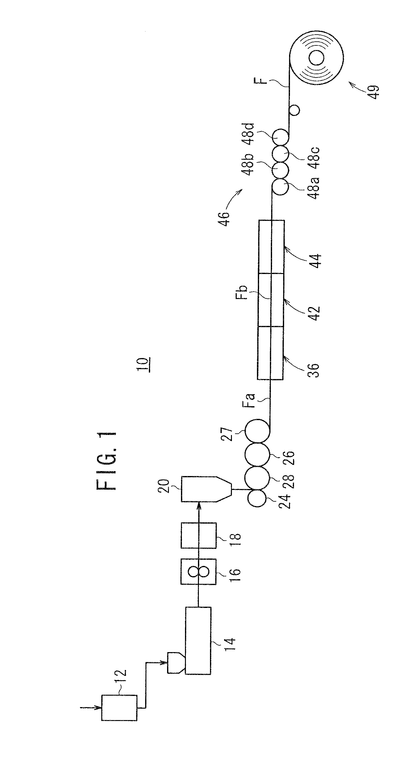
[0032]The film producing apparatus 10 shown in FIG. 1 is capable of producing a thermoplastic film F useful for a liquid crystal display device, etc. A pellet of a material for the thermoplastic film F, such as a cellulose acylate resin, a cycloolefin resin, a polycarbonate resin, or a lactone ring-containing polymer resin, is introduced to a dryer 12, and dried therein. The dried pellet is extruded by an extruder 14, and transported to a filter 18 by a gear pump 16. A contaminant in the pellet is removed by filtration with the filter 18, and a resin melt of the thermoplastic resin is extruded from a die 20. Then, the resin melt is press-formed between a first casting roll 28 and a touch roll 24, and cooled and solidified on the first casting roll 28 to prepare a film-shaped melt having a predetermined surface roughness. The film-shaped melt is transported by a second casting roll 26 and a third casting roll 27, to obtain an unstretched film Fa. The unstretched film Fa may be then wound and removed. Alternatively, the unstretched film Fa may be successively introduced to a transverse stretching portion 42 for long-span stretching. Even in a case where the unstretched film Fa is once wound and removed, and then introduced to the transverse stretching portion 42, the advantageous effects of the present invention are achieved.
[0033]In the transverse stretching portion 42, as shown in FIG. 1, the unstretched film Fa is stretched in the width direction perpendicular to the transporting direction to prepare a transversely stretched film Fb. A preheating portion 36 and a heat-fixing portion 44 may be disposed upstream and downstream of the transverse stretching portion 42 respectively to reduce bowing (misalignment of the optic axes) in the stretching process. The preheating temperature is preferably higher than the transverse stretching temperature, and the heat-fixing temperature is preferably lower than the transverse stretching temperature. The bowing is generally such that the width direction center of the film is concave forward in the transporting direction. When the above temperatures satisfy the conditions of [preheating temperature>stretching temperature] and [stretching temperature>afterheating temperature], the bowing can be reduced. One or both of the preheating and afterheating treatments may be carried out.
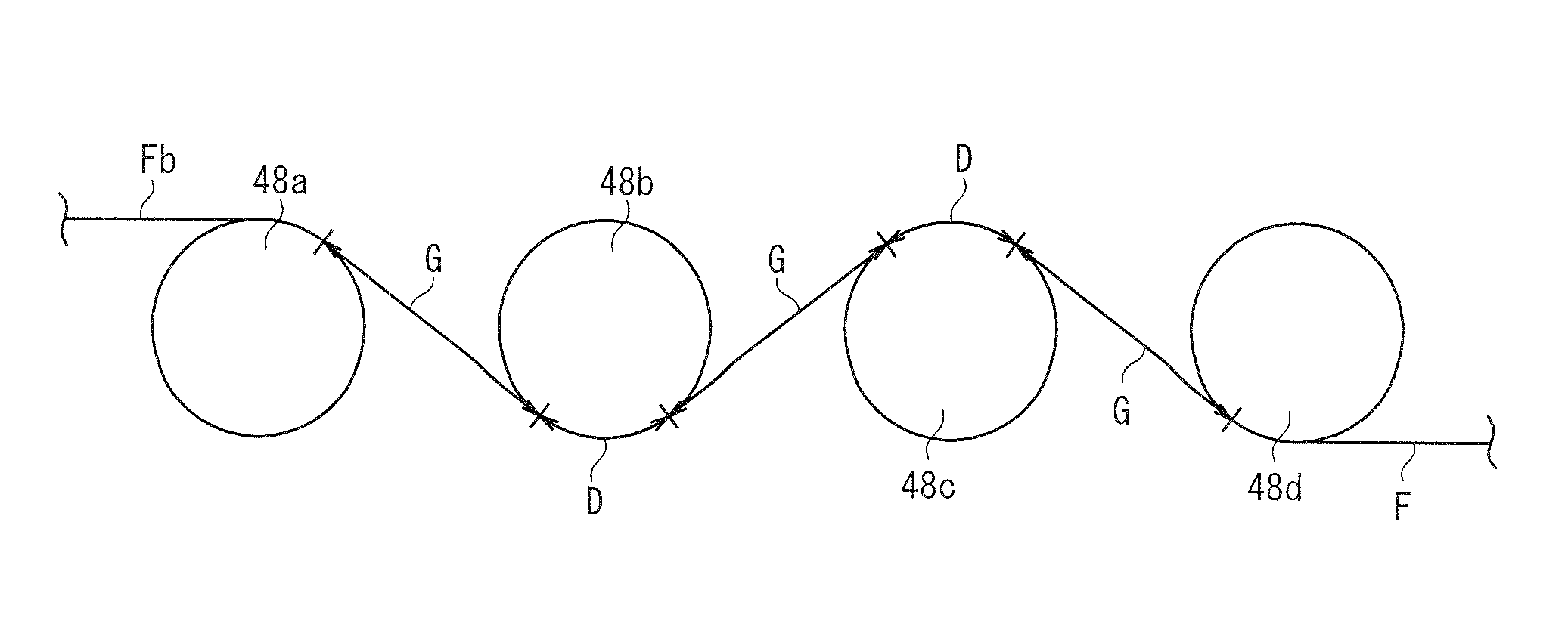
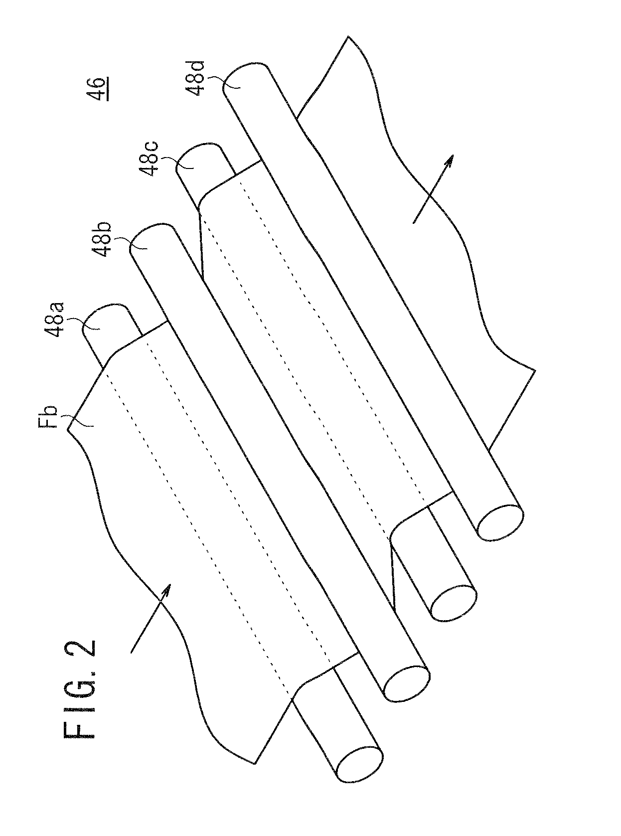
[0034]After the transverse stretching, the transversely stretched film Fb is heat-treated and shrunk in the longitudinal direction in a heat-treating zone 46. As shown in FIG. 2, the side edges of the film Fb are not fixed by a chuck, and the transversely stretched film Fb is transported by a plurality of rolls 48a to 48d such that the transversely stretched film Fb is shrunk not in the TD (transverse direction) but in the MD (longitudinal direction). As shown in FIG. 3, the rolls 48a to 48d are arranged such that the ratio (G / D) of the inter-roll distance (G) to the roll lap length (D) is 0.01 to 3. As a result, transverse shrinkage of the transversely stretched film Fb is prevented due to the friction between the film and the rolls. The transversely stretched film Fb is transported in the heat-treating zone 46 at a transporting speed (V1) of the entry-side roll 48a and at a transporting speed (V2) of the exit-side roll 48d such that the ratio (V2 / V1) of the exit-side transporting speed (V2) to the entry-side transporting speed (V1) is 0.6 to 0.999. Thus, the transversely stretched film Fb is longitudinally shrunk in the heat-treating zone 46.
[0035]The transversely stretched film Fb is heat-treated in the heat-treating zone, so that a thermoplastic film F having controlled orientation angle and retardations is produced as a final product. The film F is wound in a winding portion 49.
[0036]A longitudinal stretching process may be carried out before or after the transverse stretching process. The film may be longitudinally stretched such that the film is transported between a pair of nip rolls, the transporting speed of the exit-side nip roll being higher than that of the entry-side nip roll. A longitudinal stretching method may be selected depending on the ratio (L / W) of the distance L between the nip rolls to the film width W at the entry-side nip roll. When the L / W ratio is small, a longitudinal stretching method described in Japanese Laid-Open Patent Publication Nos. 2005-330411 and 2006-348114, etc. may be used. In this method, the size of a stretching machine can be reduced though the Rth of the film is often increased excessively. On the other hand, when the L / W ratio is large, a longitudinal stretching method described in Japanese Laid-Open Patent Publication No. 2005-301225, etc. may be used. In this method, the Rth of the film can be reduced though the size of a stretching machine is often increased.
[0037]FIG. 4 is a schematic structural view showing a liquid crystal display device 50 using the thermoplastic film F produced in the above manner.

Problems solved by technology

However, these methods are disadvantageous in that, for example, the resultant stretched film cannot achieve the high contrast in a liquid crystal display device, or the method is poor in productivity.
However, this method is extremely poor in productivity because the phase difference film produced by the method has a slow axis along the longitudinal direction, and thereby cannot be attached to a polarizer or a polarizing plate in a roll-to-roll manner.
However, in the case of using these films, as the screen size of the liquid crystal display device is increased, the contrast difference (contrast unevenness) between the center and edge of the screen is increased by a thermotreatment, and also light leakage is increased.

Method used


Image

  • Heat treatment of thermoplastic film, and thermoplastic film and method for producing the same
  • Heat treatment of thermoplastic film, and thermoplastic film and method for producing the same
  • Heat treatment of thermoplastic film, and thermoplastic film and method for producing the same

Examples


examples

[0310]The characteristics of the present invention will be described more specifically with reference to Examples and Comparative Examples. Materials, amounts, ratios, treatment contents treatment procedures, and the like, used in Examples, may be changed without departing from the scope of the present invention. The following embodiments are, therefore, to be considered in all respects as illustrative and not restrictive.

1. Preparation of Unstretched Film

(1) Cellulose Acylate Film

(a) Melt Film Forming

[0311]A cellulose acetate propionate film #CM according to Example 1 of Japanese Laid-Open Patent Publication No. 2007-98917 was prepared. The film #CM had a thickness of 100 μm and a Tg of 146° C.

[0312]A cellulose acylate film #CN according to Example 101 in Example B of Japanese Laid-Open Patent Publication No. 2007-169588 was prepared. The film #CN had a thickness of 100 μm and a Tg of 131° C.

(b) Solution-Cast Film Forming

[0313]A cellulose acetate propionate film #CS according to Fi...


PUM

PropertyMeasurementUnit
Raaaaaaaaaaa
surface roughnessaaaaaaaaaa

Abstract

A thermoplastic film is transversely stretched, and then transported in a heat-treating zone (46) such that the ratio (G / D) of an inter-roll distance (G) to a roll lap length (D) is 0.01 to 3, and the ratio (V2 / V1) of an exit-side transporting speed (V2) to an entry-side transporting speed (V1) is 0.6 to 0.999. The thermoplastic film is heat-treated in the heat-treating zone (46) at (Tg−20)° C. to (Tg+50)° C., in which Tg is the glass transition temperature of the film. The heat-treated thermoplastic film exhibits an Rth / Re ratio of at least 0.5 and less than 1, an Rth / Re ratio range of 0.01 to 0.1 in the width direction, and a thermal dimensional change of 0.001% to 0.3% under conditions of 80° C. and 200 hours.

Description

BACKGROUND OF THE INVENTION[0001]1. Field of the Invention[0002]The present invention relates to a method for heat-treating a thermoplastic film useful for a polarizing plate, an optical compensatory film for a liquid crystal display panel, an antireflection film, a liquid crystal display device, etc., and to a thermoplastic film and a method for producing the same.[0003]2. Description of the Related Art[0004]For the purpose increasing the viewing angle of a liquid crystal display device, a thermoplastic film is stretched to generate an in-plane retardation and a thickness direction retardation, and used as a phase difference film for the device. Particularly in recent years, a phase difference film capable of achieving a high contrast in a liquid crystal display device has been required to apply TN display mode to televisions.[0005]Stretched thermoplastic films have been known as the phase difference film. The thermoplastic film can be stretched by using a longitudinal stretching m...

Claims


Application Information

Patent Timeline
Patent Type & Authority Patents(United States)
IPC IPC(8): B29C71/00B29D7/01B29D11/00B29C48/08B29C48/405B29C48/41B29C55/08B29K1/00B29K45/00B29K69/00B29L7/00B29L11/00G02B5/30G02F1/13363
CPCB29C41/26B29C41/28B29C55/08B29C55/12B29C71/02B29K2001/00B29K2001/12B29K2023/38B29K2105/256B29K2995/0034G02F1/133634Y02P20/582B29C48/08B29C48/305B29C48/37B29C48/387B29C48/69B29C48/693B29C48/76B29C48/41B29C48/405B29C55/04B29C51/04
Inventor HASHIMOTO, KIYOKAZUYOSHIDA, TETSUYAOTOSHI, MASAAKI
Owner FUJIFILM CORP
Why Eureka
Try Eureka