Wiper blade

a technology of a wand and a blade body, which is applied in the field of wands, can solve the problems of limited lifespan in which wands are able to perform their functions effectively, impair driver visibility, and continue use, and achieve the effect of fast and easy transition and extended lifespan

Active Publication Date: 2012-04-17
GUTTILLO PAUL
View PDF10 Cites 2 Cited by
  • Summary
  • Abstract
  • Description
  • Claims
  • Application Information

AI Technical Summary

Benefits of technology

[0007]The wiper blade disclosed herein includes: a body that attaches to a backing; an outer blade; an inner blade; and a tab; wherein the outer blade surrounds and protects the inner blade until a user removes the outer blade by applying force to the tab, exposing the inner blade for use. Accordingly, the wiper blade disclosed herein has an extended lifespan over traditional wiper blades and a user can quickly and easily transition from using the outer blade to the inner blade when desired.
[0009]It is further contemplated that in another embodiment of the wiper blade, the number of blades may be increased such that there is an inner blade, an outer blade and one or more intermediate blades, each of which may be exposed by the removal of an adjacent blade.
[0010]An advantage of the wiper blade is a longer lifespan when compared to traditional wiper blades.
[0012]A further advantage of the wiper blade is a quick change mechanism for switching from the primary to the inner blade.
[0013]Yet another advantage of the wiper blade is increased vehicle operation visibility and safety.

Problems solved by technology

Wiper blades have a limited lifespan in which they are able to perform their function effectively.
In fact, once a wiper blade has reached the end of its useful lifespan, continued use can often impair the driver's visibility by creating streaks and smearing debris.
One impediment to maintaining effective wiper blades is, while they are not necessarily used each time a vehicle is operated, the wiper blades themselves may degrade during their non-use due to their exposure to the elements to which the vehicle is exposed.
As a result, it is not uncommon for an operator of a vehicle to first recognize that the current wiper blades are past their lifespan only after they are needed and cannot perform as required.
Moreover, due to the time required to change a typical wiper blade, a vehicle operator may not want to make the replacement during the inclement weather that brought about the necessity for the wiper blade change.

Method used


Image

  • Wiper blade
  • Wiper blade
  • Wiper blade

Examples


Embodiment Construction

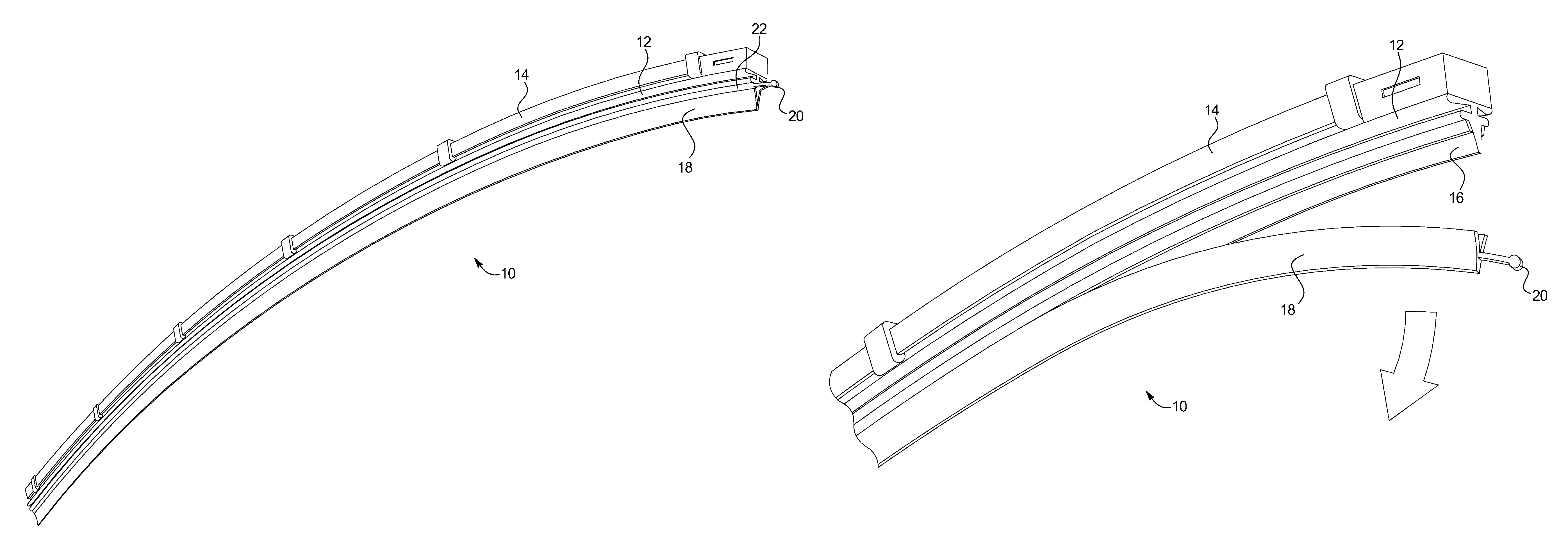
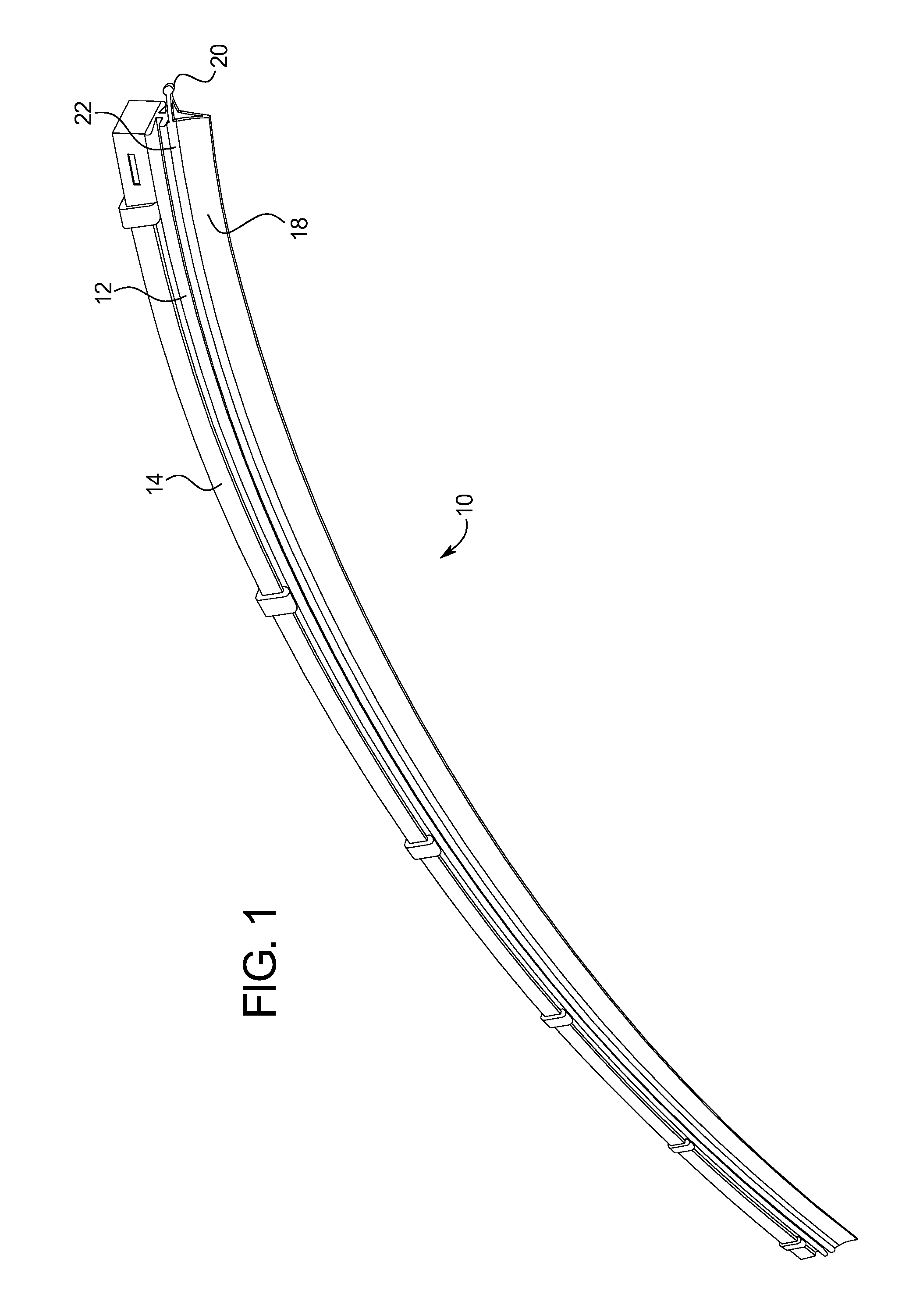
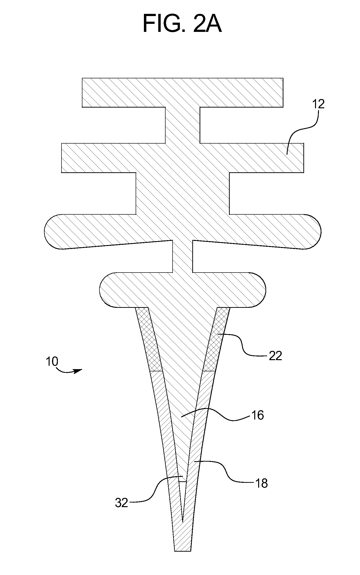
[0022]The wiper blade 10 shown in FIG. 1 includes a body 12 for mating to a backing 14 and an outer blade 18 surrounding an enclosed inner blade 16 (shown in FIGS. 2-4). The outer blade 18 is removeably secured to the wiper blade 10 such that the outer blade 18 can be removed and disposed to uncover the inner blade 16 for use. As shown, a tab 20 provides a convenient location for a user to apply the force required to remove the outer blade 18 from the wiper blade 10. The process for removing the outer blade 18, as described herein, is fast and easy, enabling the user to quickly change to the inner blade 16 when desired. As a result, the outer blade 18 may be used until the end of its lifespan before being discarded.

[0023]As shown in FIGS. 1, 2A, 2B and 5, prior to removal, the outer blade18, directly or indirectly, surrounds and encloses the inner blade 16. Thus, the inner blade 16 is not exposed to the elements and is protected from degradation by the outer blade 18. Accordingly, i...


PUM


Abstract

A wiper blade includes a first blade and a second blade surrounding the first blade, such that the first blade is not exposed for use, wherein the removal of the second blade exposes the first blade for use. In another embodiment, a wiper blade includes a body, an inner blade attached to the body, an outer blade bonded to the body or inner blade, a gripping mechanism attached to the outer blade and a removal mechanism located between the inner blade and outer blade, wherein the removal mechanism is attached to the gripping mechanism.

Description

CROSS-REFERENCE TO RELATED APPLICATIONS[0001]This application claims the benefit of U.S. Provisional Application No. 61 / 247,159, filed on Sep. 30, 2009, the entirety of which is incorporated herein by reference.BACKGROUND OF THE INVENTION[0002]The present subject matter relates generally to a wiper blade. More specifically, the present invention relates to an automotive wiper blade having a tear off outer blade and a secondary inner blade.[0003]The safe operation of automotives is highly dependant on the operator's ability to see the road. Wiper blades help increase visibility in inclement conditions and, as a result, are an integral component of vehicle safety. Wiper blades have a limited lifespan in which they are able to perform their function effectively. In fact, once a wiper blade has reached the end of its useful lifespan, continued use can often impair the driver's visibility by creating streaks and smearing debris.[0004]One impediment to maintaining effective wiper blades i...

Claims


Application Information

Patent Timeline
Patent Type & Authority Patents(United States)
IPC IPC(8): B60S1/38B60S1/28
CPCB60S1/38B60S2001/3829B60S2001/3843
Inventor GUTTILLO, PAUL
Owner GUTTILLO PAUL
Why Eureka
Try Eureka