Method for templateless foundation installation

Inactive Publication Date: 2012-04-17
SHELL OIL CO
View PDF96 Cites 5 Cited by
  • Summary
  • Abstract
  • Description
  • Claims
  • Application Information

AI Technical Summary

Benefits of technology

[0013]Other aspect of the present invention include an improved pile having an interior load shoulder positioned below a tendon load connect

Problems solved by technology

Further, the tendons must transmit this static load while subject to additional loads which have significant cyclical components driven by environmental forces of wind, wave and current on the hull and tendons.
However, this was found to be impractical due to both operational constraints and the risks, difficulties, and expense of designing the tubular goods for the internal pressure in these members as flowlines and the axial load as mooring members.
However, the tendon-to-receptacle, to-template (and over)-to pile sleeve, to-pile, to-ocean floor load path of the conventional template based foundation system is an inefficient load transfer scheme.
This also commits a large quantity of steel to the template and creates handling difficulties for transporting and deploying the massive template.
Further, the lateral spacing between the tendon receptacles and the pile sleeves which introduces these inefficiencies also exacerbates the fatigue response of the template based foundation system.
This does reduce the material requirements, but does not alleviate the inefficiencies in load transfer discussed above.

Method used


Image

  • Method for templateless foundation installation
  • Method for templateless foundation installation
  • Method for templateless foundation installation

Examples


Embodiment Construction

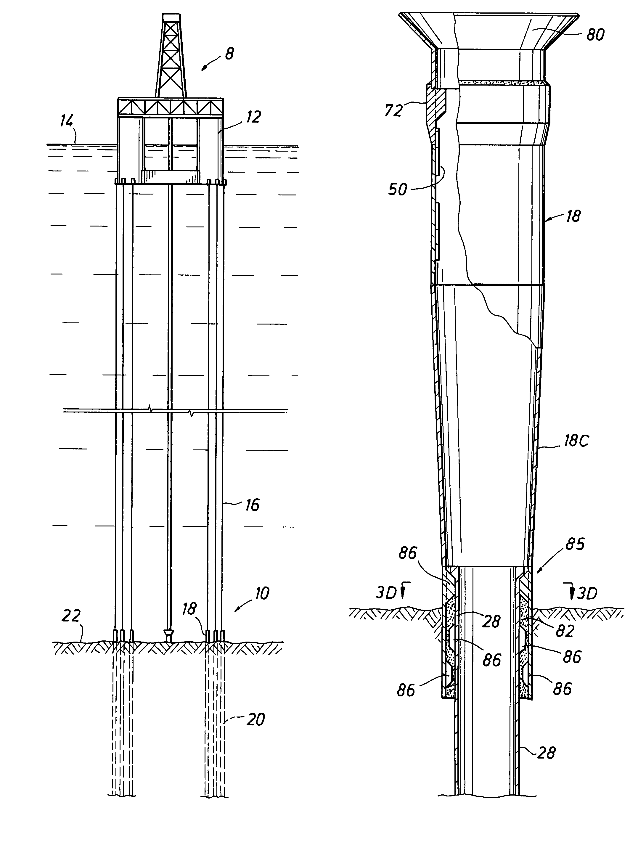
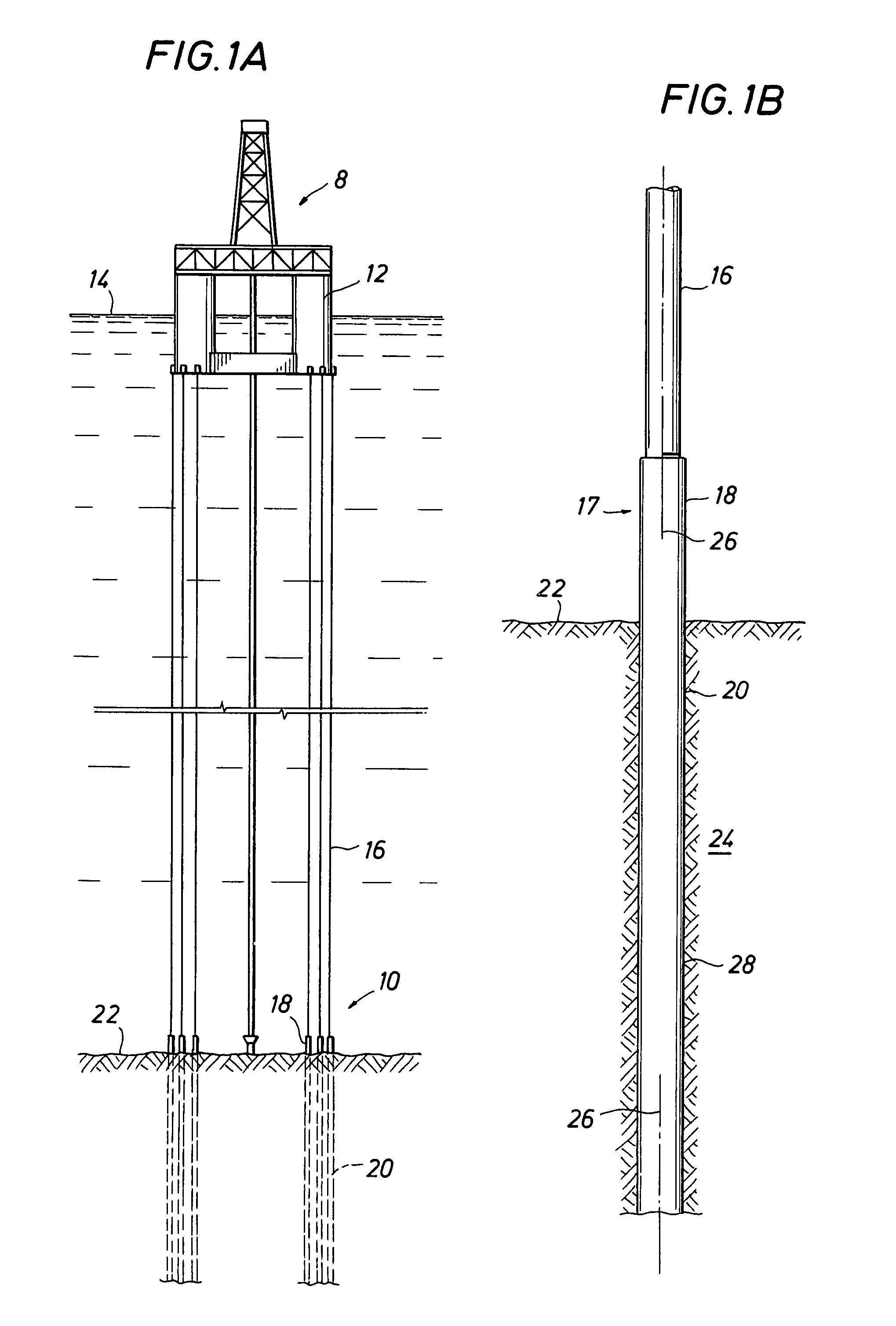
[0027]FIG. 1A generally illustrates a TLP 8 having buoyant hull 12 riding on ocean surface 14 and tethered in place about tendons 16 secured to the foundation system 10 of the present invention. Foundation system 10 includes tendon receptacles 18 into which the bottom of tendons 16 are secured and piles 20 which extend deep into ocean floor 22.

[0028]FIG. 1B is a more detailed illustration of one of tendons 16 latched into a tendon receiving load connection 17, here in the form of tendon receptacle 18, provided on pile 20. In this embodiment, pile 20 combines an elongated cylindrical member or pile member 28 with an integrally formed tendon receptacle 18. Elongated cylindrical member 28 extends deeply into sediment 24 at ocean floor 22 to such a depth as which the skin friction between the sediment and the exterior of the pile is competent to securely restrain, with an adequate margin of safety, the axial load of restraining buoyant hull 12 of TLP 8 in place and drawn below its natur...


PUM


Abstract

A method of installing a foundation system for securing the tendons of a TLP to the ocean floor. The foundation system is installed in templateless operations in which a pile is secured to the ocean floor and a tendon receptacle is secured to the pile such that the load from a tendon secured therein is transferred to the ocean floor through coaxially aligned load paths of tendon-to-tendon receptacle-to-pile-to-ocean floor.

Description

[0001]This is a continuation of application Ser. No. 08 / 236,295 filed May 2, 1994, Now Abandoned.BACKGROUND OF THE INVENTION[0002]The present invention relates to deepwater platform foundations. More particularly, it relates to a tension leg platform foundation anchored to the ocean floor through a plurality of piles.[0003]As used herein, a “tension leg platform” or TLP refers to any buoyant structure tethered to the ocean floor through substantially vertical tendons tensioned to draw the buoyant structure below its normal floating draft. Various embodiments include a full scale TLP having full drilling facilities, a tension leg well platform (“TLWP”) having only a scaled down “completion” rig, a tension leg well jacket (“TLWJ”) designed to accept well operations from an auxiliary vessel, or any other tendon deploying variation.[0004]Tendons connect the buoyant hull to a foundation system at the ocean floor and are tensioned to draw the buoyant hull below its normal floating draft. ...

Claims


Application Information

Patent Timeline
IPC IPC(8): E02D13/00B63B21/50E02D5/80E02D7/02E02D7/14E02D7/28E02D13/10E02D27/50
CPCB63B21/502E02D5/80E02D7/02E02D7/14E02D7/28E02D13/10E02D27/50
Inventor DOYLE, JR., EARL HOWARDHUETE, DAVID ARMSTRONGGARSIDE, RICHARDSNYDER, DALE RICHARD
Owner SHELL OIL CO
Why Eureka
Try Eureka