Connector stabilizing coupling body assembly

a coupling body and connector technology, applied in the direction of coupling device details, coupling device connections, two-pole connections, etc., can solve the problems of affecting the stability of the connection, the integrity of the cable/connector connection, and the damage to the connector,

Inactive Publication Date: 2012-04-17
COMMSCOPE TECH LLC
View PDF24 Cites 40 Cited by
  • Summary
  • Abstract
  • Description
  • Claims
  • Application Information

AI Technical Summary

Benefits of technology

[0023]The stabilizing contact may be enhanced with respect to a longitudinal axis direction, to also improve the mechanical tear off strength of the interconnection between the coaxial connector 23 and coaxial cable 13, by applying a plurality of inward projecting protrusion(s) 31 to the inner diameter of the jacket grip 15. Further, the inward projecting protrusion(s) 31 may improve an anti rotation coaxial connector 23 to coaxial cable 13 characteristic of the stabilizing contact.
[0025]The coupling body 3, jacket grip 15 and stabilizing body 17 may be cost effectively manufactured via injection molding, for example of polymeric material. The injection molding may be further optimized with respect to materials consumption and reduction of molding defects such as warp and sink by forming areas of the stabilizing body 17 with a plurality of inward extending support fin(s) 37, rather than a conventional solid configuration with significant material thickness areas where material strength requirements of the structure are reduced. Further, to simplify mold design and mold separation mechanics, thread(s) 25 and / or inward / outward projecting retaining lip 33 and / or retention burr 35 may be applied as arc segments 39 rather than continuous annular features. Thereby, upon rotation of the respective mold portion and / or the molded component, axial mold separation is enabled.

Problems solved by technology

Rotation of the coaxial cable and coaxial connector with respect to each other may damage the connector, the cable and / or the integrity of the cable / connector inter-connection.
Further, once installed, twisting, bending and / or vibration applied to the interconnection over time may degrade the connector to cable interconnection and / or introduce PIM.
Therefore, any stabilizing effect obtained from the environmental seal is limited.

Method used


Image

  • Connector stabilizing coupling body assembly
  • Connector stabilizing coupling body assembly
  • Connector stabilizing coupling body assembly

Examples


Embodiment Construction

[0017]The inventor has recognized that movement and / or skewing of alignment between the connector and coaxial cable may generate unacceptable levels of PIM and / or otherwise compromise the electromechanical interconnection, for example as contact surfaces shift relative to one another and / or less than uniform circumferential contact occurs between the electrical contacting elements of the connector and the inner and / or outer conductors.

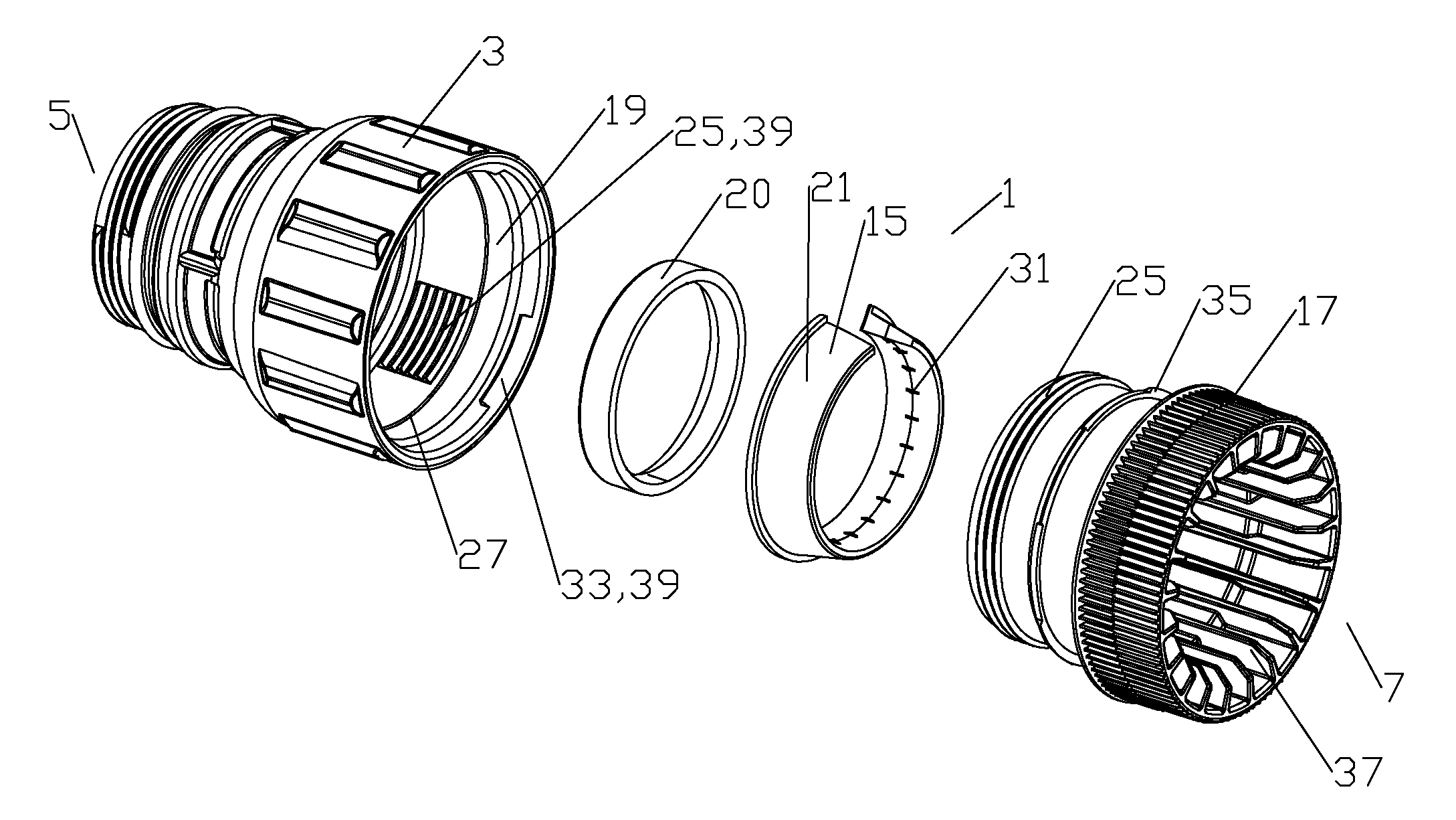
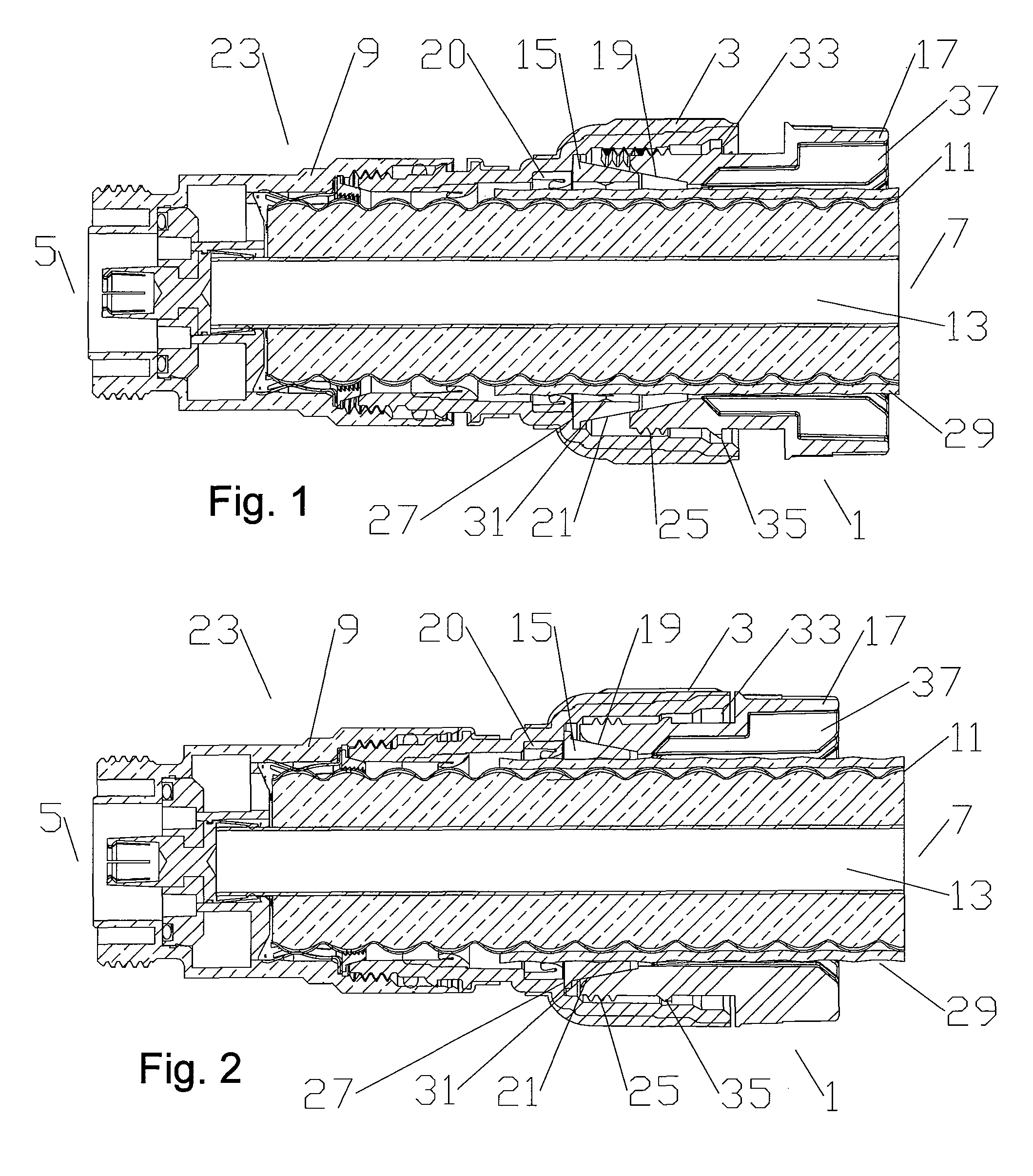
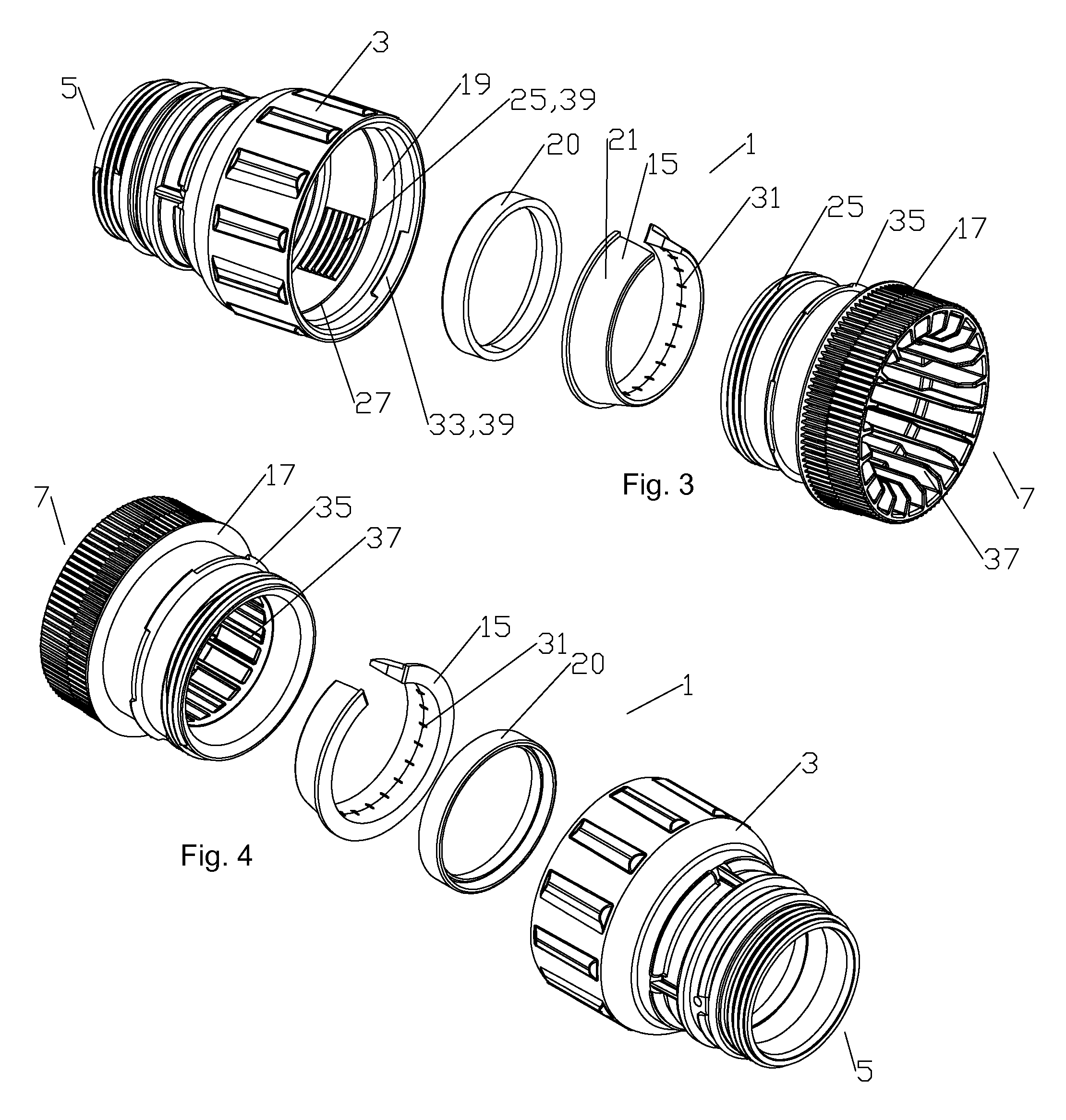
[0018]A first embodiment of a coupling body assembly 1 with a connector to cable interconnection stabilizing functionality is demonstrated in FIGS. 1-4. As best shown in FIGS. 3 and 4, the coupling body assembly 1 includes a coupling body 3 dimensioned to couple at a connector end 5 of the coupling body 3 with a cable end 7 of a coaxial connector body 9.

[0019]One skilled in the art will appreciate that connector end 5 and cable end 7 are applied herein as identifiers for respective ends of both the overall assembly and also of discrete elements of the ...


PUM

PropertyMeasurementUnit
outer diameteraaaaaaaaaa
diameteraaaaaaaaaa
inner diameteraaaaaaaaaa

Abstract

A stabilizing coupling body assembly for a coaxial connector is provided with a coupling body dimensioned to couple at a connector end of the coupling body with a cable end of the connector. A jacket grip of rigid material is retained between the coupling body and a stabilizing body coupled to a cable end of the coupling body. An outer diameter of the jacket grip abuts an annular wedge surface of the stabilizing body. The wedge surface is provided with a taper between a maximum diameter proximate a connector end of the jacket grip and a minimum diameter proximate a cable end of the annular wedge surface. The jacket grip is driven radially inward as the stabilizing body is advanced axially towards the coupling body. Methods of manufacture include forming elements of the coupling body assembly via injection molding.

Description

BACKGROUND[0001]1. Field of the Invention[0002]This invention relates to electrical cable connectors. More particularly, the invention relates to a connector stabilizing coupling body assembly for improving connector to cable retention and passive intermodulation distortion (PIM) electrical performance.[0003]2. Description of Related Art[0004]Coaxial cable connectors are used, for example, in communication systems requiring a high level of precision and reliability.[0005]To create a secure mechanical and optimized electrical interconnection between the cable and the connector, it is desirable to have generally uniform, circumferential contact between a leading edge of the coaxial cable outer conductor and the connector body. A flared end of the outer conductor may be clamped against an annular wedge surface of the connector body, via a coupling body. Representative of this technology is commonly owned U.S. Pat. No. 5,795,188 issued Aug. 18, 1998 to Harwath.[0006]Alternative forms of...

Claims


Application Information

Patent Timeline
Patent Type & Authority Patents(United States)
IPC IPC(8): H01R9/05
CPCH01R4/5025H01R9/05H01R13/622Y10T29/49169H01R24/56H01R2103/00H01R13/6277H01R24/566H01R13/646
Inventor PAYNTER, JEFFREYLOW, DAVIDBUENZ, LARRY
Owner COMMSCOPE TECH LLC
Why Eureka
Try Eureka