Methods and apparatus for foam control in a vacuum filtration system
What is AI technical title?
AI technical title is built by Patsnap AI team. It summarizes the technical point description of the patent document.
a vacuum filtration and vacuum bottle technology, applied in the field of liquid filtration, can solve the problems of unstable devices, prone to tipping, and various inherent challenges of processes, and achieve the effect of reducing splashing and foaming
Inactive Publication Date: 2012-04-17
FOXX LIFE SCI
View PDF98 Cites 8 Cited by
Summary
Abstract
Description
Claims
Application Information
AI Technical Summary
This helps you quickly interpret patents by identifying the three key elements:
Problems solved by technology
Method used
Benefits of technology
Benefits of technology
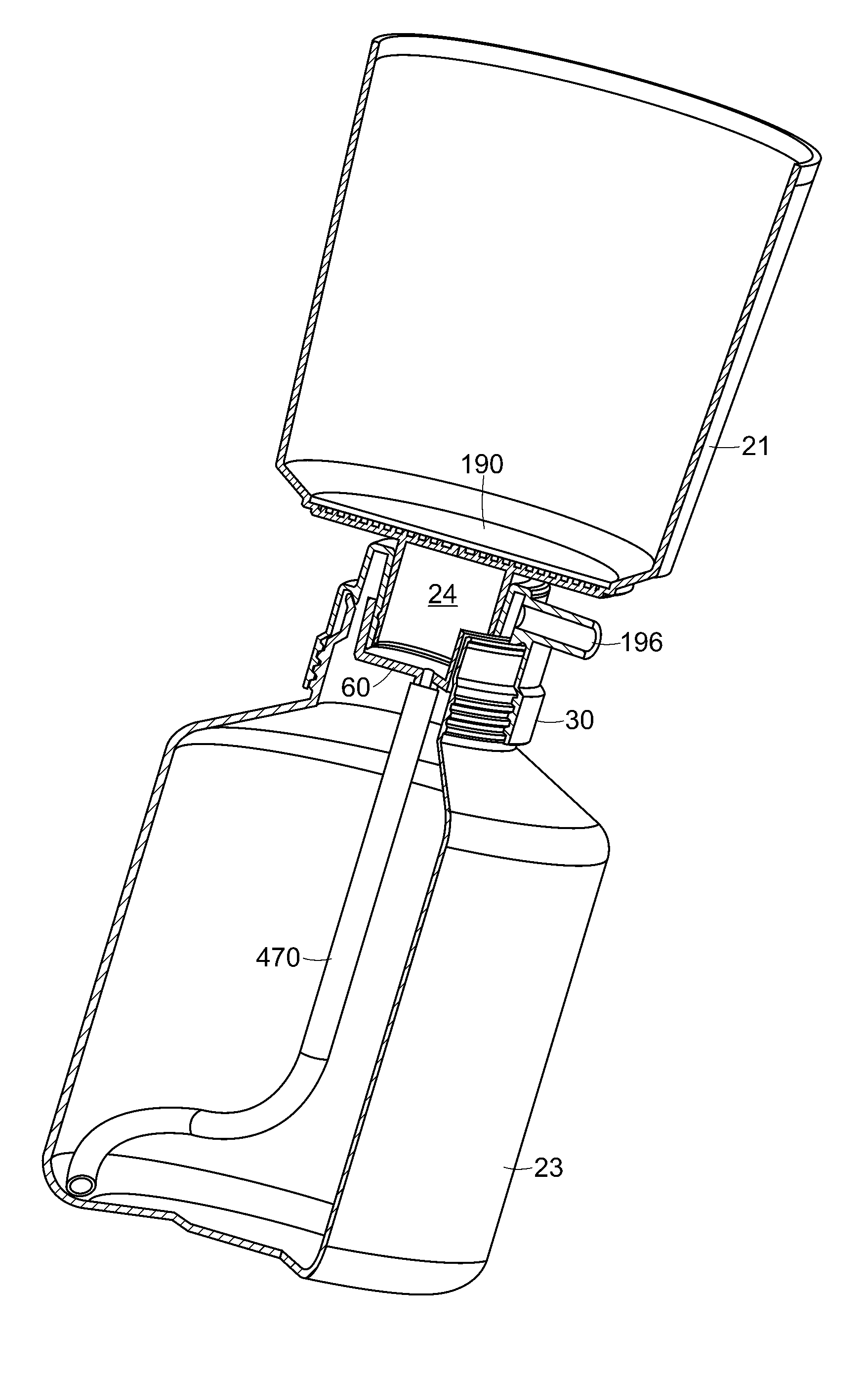
[0006]A liquid filtering assembly has an upper sample reservoir for receiving a volume of sample liquid. A sample filter is positioned proximate a bottom of the sample reservoir for mechanically filtering the sample liquid. A lower storage bottle receives filtered sample liquid from the sample reservoir. A vacuum in fluid communication with the lower storage bottle serves to draw sample liquid through the sample filter into the storage bottle. A flow diverter is positioned to receive sample liquid drawn through the sample filter and to direct the sample liquid onto a sidewall of the lower storage bottle. Flow along the sidewall advantageously reduces splashing and foaming.
[0008]A base receives an inserted filter assembly to hold the assembly securely above a work surface. The base may include a weighted bottom to avoid tipping over. The base can be advantageously designed to couple a vacuum to the vacuum collar. A fluid conduit through the base connects a vacuum inlet port with a vacuum outlet port. The vacuum outlet port is arranged in a cradle for connection to the liquid filter assembly. The cradle is on a support arm secured to the weighted bottom of the base. The cradle is movable relative to the weighted bottom so as to adjustably hold the liquid filter assembly at a tilted non-vertical angle. Adjustment may be provided by flexibility of the support arm in one embodiment. Alternatively, the cradle may be pivotable with respect to the support arm. The tilted assembly can urge flow of filtrate along the sidewall to reduce splashing and foaming.
[0009]Splashing and foaming can be further avoided by controlling the pressure level of the vacuum. For this purpose, it is advantageous to provide a vacuum controller accessible atop the work surface to regulate the vacuum. In a specific embodiment, the base couples the vacuum to the liquid filter assembly and a vacuum controller is provided on the base to regulate fluid flow through a fluid conduit that connects a vacuum inlet port on the base to a vacuum outlet port. The vacuum outlet port may be arranged in a cradle for connection to the liquid filter assembly. The vacuum controller may include a knob having an off position for venting the fluid conduit to the atmosphere so that no vacuum pressure is provided to the lower storage bottle.
[0010]Methods of the present invention for filtering liquid samples involve securing a filter assembly above a work surface. The filter assembly includes an upper reservoir above a filter and a storage bottle below the filter for receiving filtered liquid drawn through the filter. A liquid sample is deposited in the upper reservoir and a vacuum applied underneath the filter to draw liquid through the filter. A vacuum controller is adjusted to regulate the applied vacuum so as to reduce foaming of the filtered liquid sample. Other actions that may be taken include tilting the filter assembly to cause the filtered liquid to flow along a sidewall of the storage bottle. Alternatively, flow of liquid may be directed along a diverter onto the sidewall of the storage bottle or guided through a tube to the bottom of the storage bottle.
Problems solved by technology
Such products and processes have various inherent challenges.
A spill can disrupt production for up to an entire day and require use of a sanitizing laminar hood.
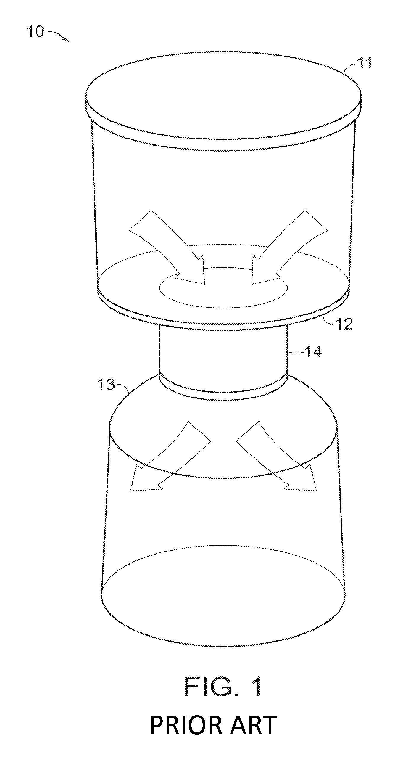
Moreover, the bottle-top filter device 10 of FIG. 1 is top heavy, especially when first filled with sample liquid, making the device unstable and prone to tipping.
The need for manual attachment of the vacuum source to the vacuum port of the vacuum collar 14 creates further problems with instability.
These issues can lead to greater risk of spillage, increased setup time, and a need for full-time supervision.
Filtrate pulled through the filter is apt to fall into the storage bottle and splash.
Splashing can cause foaming of the filtered sample.
Foam can damage cells and / or proteins, making it undesirable for filtered cell culture media to contain foam.
Method used
Image
Click on the blue label to locate the original text in one second.
Reading with bidirectional positioning of images and text.
Examples
Embodiment Construction
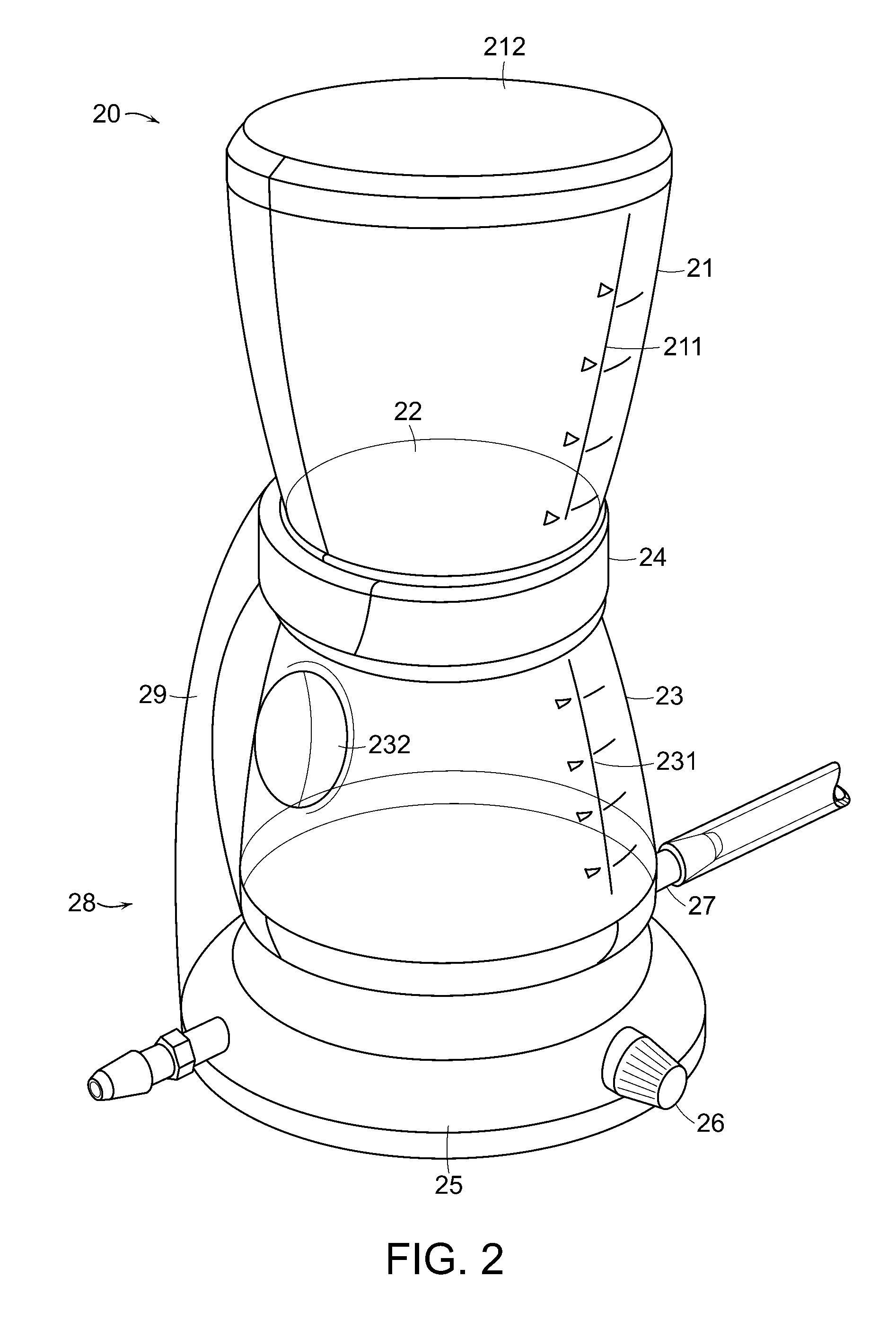
[0030]Referring now to FIG. 2, a liquid filtration system 20 includes a vacuum bottle 23. The vacuum bottle 23 is connected by a vacuum collar 24 to an upper sample reservoir 21, which together form a unified filter assembly. The filter assembly is preferably disposable and pre-sterilized. The vacuum bottle 23 may have male threads around its top opening, which screw into female threads of the vacuum collar 24. Any other type of releasable attachment between the vacuum bottle 23 and the vacuum collar 24 could be used, such as, for example, press fit. The vacuum collar 24 likewise attaches to the bottom of the upper sample reservoir 21. Alternatively, the vacuum collar 24 may be integral with the upper sample reservoir 21. The vacuum collar 24 itself is preferably a one piece molded element, but may be made as a plurality of elements such as a top funnel portion and a bottom threaded member with a vacuum port. Possible materials for the vacuum collar include but are not limited to, a...
PUM
Property
Measurement
Unit
volume
aaaaa
aaaaa
vacuum
aaaaa
aaaaa
non-vertical angle
aaaaa
aaaaa
Abstract
A flow diverter, vacuum control and tilting of the liquid filtering system are used alternatively or in conjunction to reduce foam production in a filtered liquid sample. A liquid filtering system includes an upper sample reservoir, a filter and a lower storage bottle. A vacuum is applied below the sample filter to draw sample liquid through the sample filter into the storage bottle. A flow diverter may be used to direct flow of the filtered liquid sample onto a sidewall of the storage bottle or guide flow to a bottom of the storage bottle. The vacuum may be regulated to reduce foaming. The liquid filtering system may be tilted to direct fluid to the sidewall of the lower storage bottle and reduce foaming.
Description
[0001]The present application claims priority from U.S. Provisional Application No 60 / 931,445, filed May 23, 2007, entitled “Vacuum Filtration Device and Method,” the full disclosure of which is hereby incorporated by reference herein. The present application further claims priority from U.S. Provisional Application No. 60 / 952,010, entitled “Vacuum Bottle”, No. 60 / 952,011, entitled “Vacuum Base,” No. 60 / 952,012, entitled “Vacuum Collar,” and No. 60 / 952,013, entitled “Vacuum Controller,” all of which were filed Jul. 26, 2007 and the full disclosures of which are hereby incorporated by reference herein. The present application is related to applications with the following titles and attorney docket numbers: “Vacuum Base and Related Methods and Apparatus for Vacuum Filtration,” Ser. No. 12 / 023,711; “Method and Apparatus for Filtrate Storage Handling,” Ser. No. 12 / 023,757; “Methods and Apparatus for Supporting a Vacuum Filtration Device,” Ser. No. 12 / 023,820 all filed on the same date h...
Claims
Application Information
Patent Timeline
Application Date:The date an application was filed.
Publication Date:The date a patent or application was officially published.
First Publication Date:The earliest publication date of a patent with the same application number.
Issue Date:Publication date of the patent grant document.
PCT Entry Date:The Entry date of PCT National Phase.
Estimated Expiry Date:The statutory expiry date of a patent right according to the Patent Law, and it is the longest term of protection that the patent right can achieve without the termination of the patent right due to other reasons(Term extension factor has been taken into account ).
Invalid Date:Actual expiry date is based on effective date or publication date of legal transaction data of invalid patent.

