Rotary evaporation with variable dosage metering

Inactive Publication Date: 2006-12-19
GENSER HANS GEORG
View PDF13 Cites 21 Cited by
  • Summary
  • Abstract
  • Description
  • Claims
  • Application Information

AI Technical Summary

Benefits of technology

[0047]It is desirable to detect any foaming in the revolving vessel and to control or adjust the flow during the dosing phase on the basis of the degree of foam formation, thus making it possible to optimally evapora

Problems solved by technology

In a rotary evaporator incorporating that type of pendulum suspension the weight of the operating flask is thus counterbalanced only by the buoy

Method used


Image

  • Rotary evaporation with variable dosage metering
  • Rotary evaporation with variable dosage metering
  • Rotary evaporation with variable dosage metering

Examples


Embodiment Construction

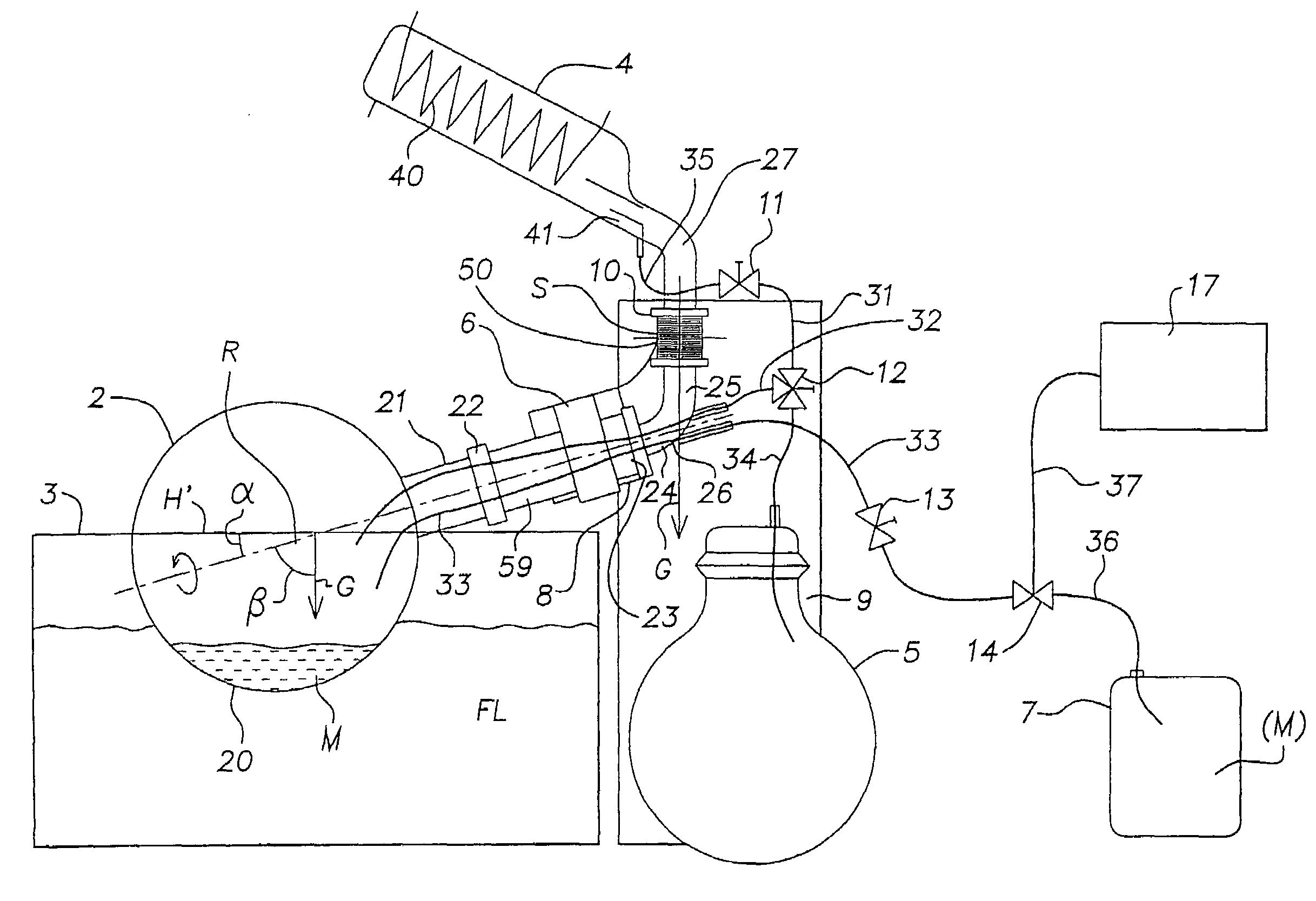
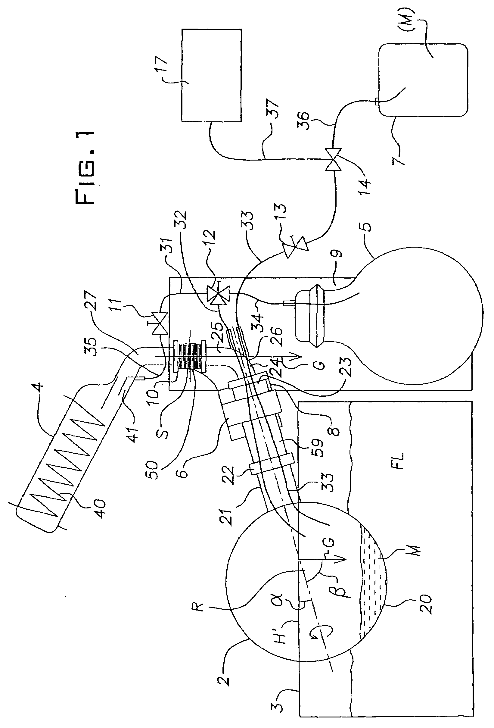
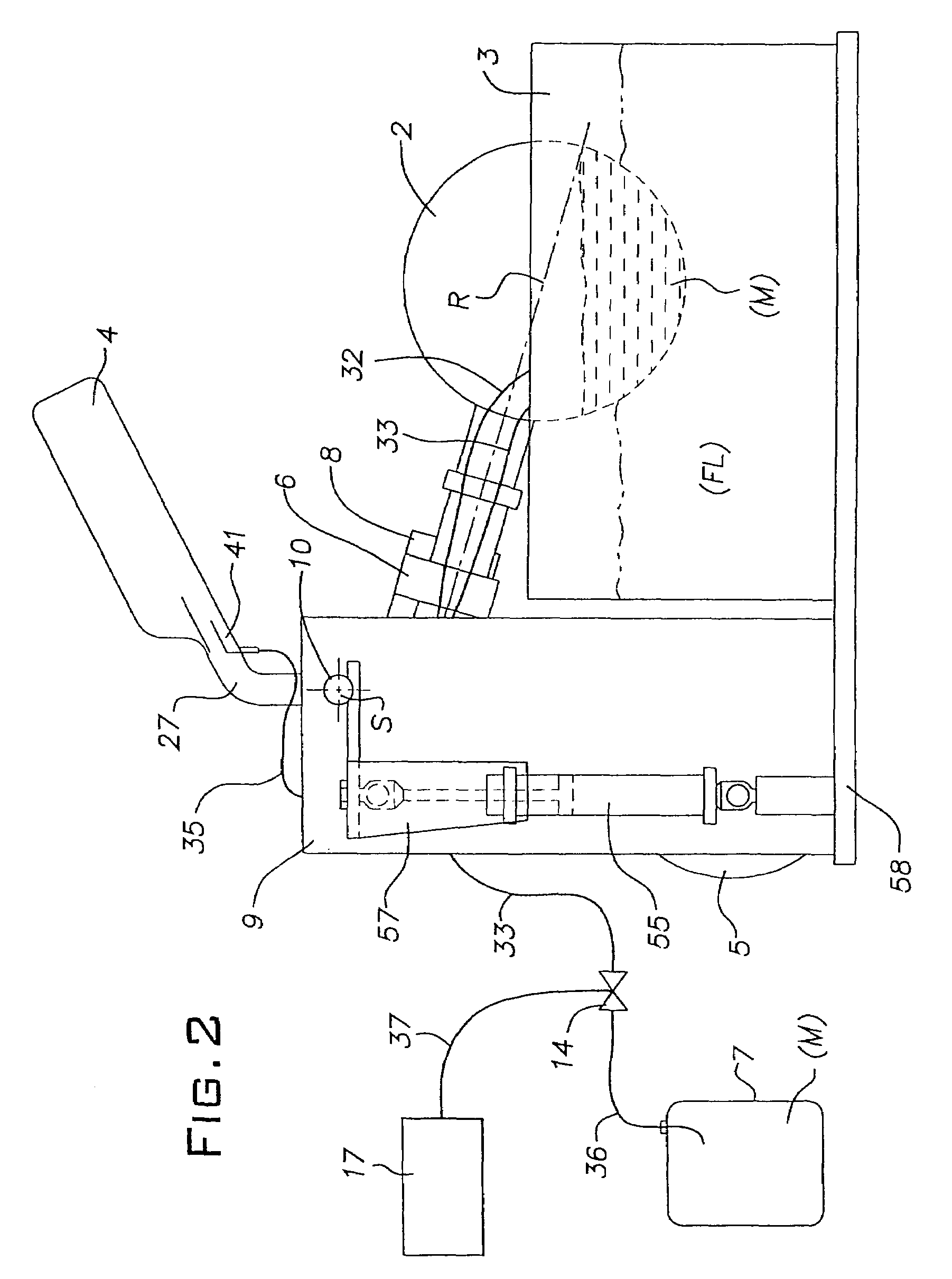
[0057]The rotary evaporator per FIG. 1 and FIG. 2 encompasses a revolving vessel (or working vessel or rotating flask) 2 which can be rotated (turned) by means of a drive system 6 around an axis of rotation R (center of rotation) and in which the substance(s) to be evaporated can be introduced. The revolving vessel 2 per FIGS. 1 and 2 is preferably designed to be rotationally symmetrical to the axis of rotation R as the axis of symmetry, making it, when empty, rotatable around its main axis of inertia without any imbalance. The revolving vessel 2 includes an essentially spherical receptacle 20 designed to hold a product M containing liquid or particulate substance(s) to be evaporated, and, extending from an opening in the spherical receptacle 20, a neck 21 which by way of a flange 22 connects to a sleeve-type shaft 59 that is or can be rotated by the drive system 6.

[0058]For rotating the revolving vessel 2, the drive system 6 includes an electric drive unit or motor, not illustrated...


PUM


Abstract

Method and system for evaporating at least one substance. During at least one dosing phase (TG) a predefined or predefinable quantity of a product (M) which contains at least one substance to be evaporated is imported via a feed system (7, 14, 17, 33, 36) into a revolving vessel (2). The revolving vessel is rotated around an axis of rotation (R) and appropriate process conditions for the evaporation of at least one substance are generated or maintained. The flow (F) of the product (M) is automatically controlled or regulated by the feed system (14, 17) during the dosing phase (TG) in particular as a function of at least one process parameter and/or of at least one characteristic property of the product. The product (M) is imported into the revolving vessel (2) in the course of the dosing phase only during predefined feed periods (t1, t2) that are interrupted by intervening intervals and especially idle intervals (t1, t2). The flow or imported quantity of the product is less during the intervening intervals by at least a factor of 10 and preferably at least by a factor of 20 than during the feed periods and is essentially zero during the idle intervals. The time duration of the feed periods and/or of the intervening intervals is or can be modified during the dosing phase.

Description

BACKGROUND OF THE INVENTION[0001]This invention relates to a method and a system for evaporating at least one substance.[0002]There have been prior-art systems, referred to as rotary evaporators, serving for the evaporation of substances and especially of solvents in the process of concentrating or distilling pharmaceutical or chemical products. In these prior-art rotary evaporators the liquid substances to be evaporated are introduced into the interior space of a rotating flask (evaporating vessel) typically designed to rotate within a thermal bath. As the rotating flask revolves, a thin film of liquid forms on the inside of the rotating flask from which film the substances, in particular the solvent, will then evaporate. A certain amount of the substance, i.e. of the solvent, also evaporates directly from the surface level of the liquid in the rotating flask. From the rotating flask the vapor travels through a vapor conduit toward a condenser where it is reprecipitated by condensa...

Claims


Application Information

Patent Timeline
IPC IPC(8): B01D1/22B01D3/42B01D3/08
CPCB01D3/085Y10S159/04
Inventor GENSER, HANS GEORG
Owner GENSER HANS GEORG
Why Eureka
Try Eureka