Force transmission device with a rotational speed adaptive damper and method for improving the damping properties

a transmission device and adaptive damper technology, applied in the direction of fluid couplings, rotary clutches, gearing, etc., can solve the problem of not being able to achieve the insulation effect, which is actually intended, and achieve the effect of optimal driving properties

a transmission device and adaptive damper technology, applied in the direction of fluid couplings, rotary clutches, gearing, etc., can solve the problem of not being able to achieve the insulation effect, which is actually intended, and achieve the effect of optimal driving properties

US8161740B2Active Publication Date: 2012-04-24SCHAEFFLER TECH AG & CO KG

Image

  • Force transmission device with a rotational speed adaptive damper and method for improving the damping properties
  • Force transmission device with a rotational speed adaptive damper and method for improving the damping properties
  • Force transmission device with a rotational speed adaptive damper and method for improving the damping properties

Examples


Embodiment Construction

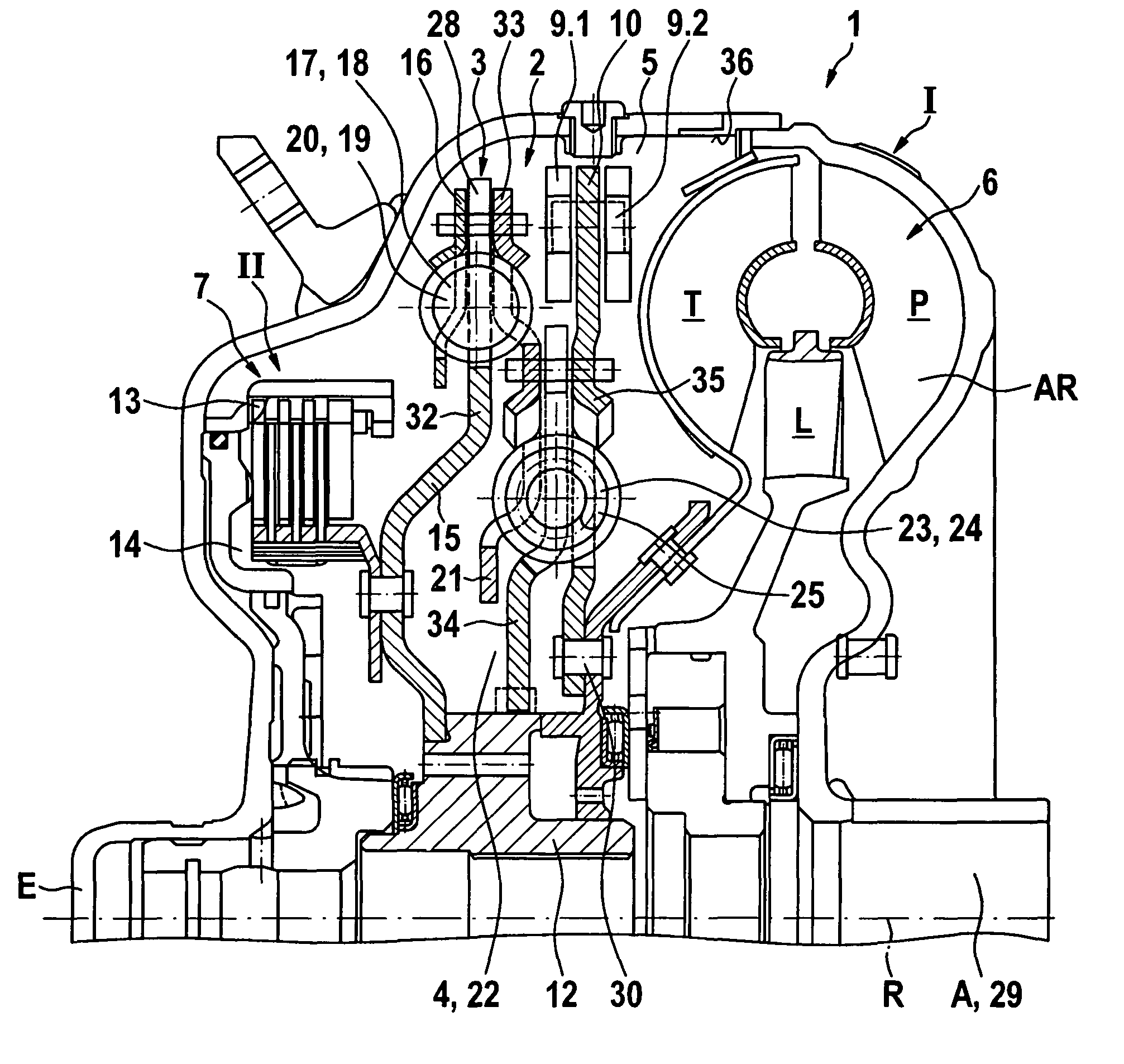
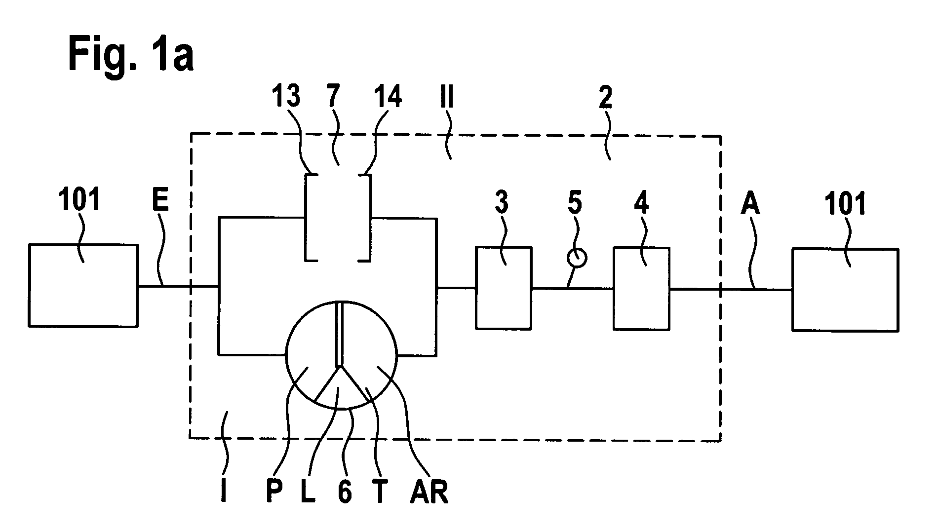
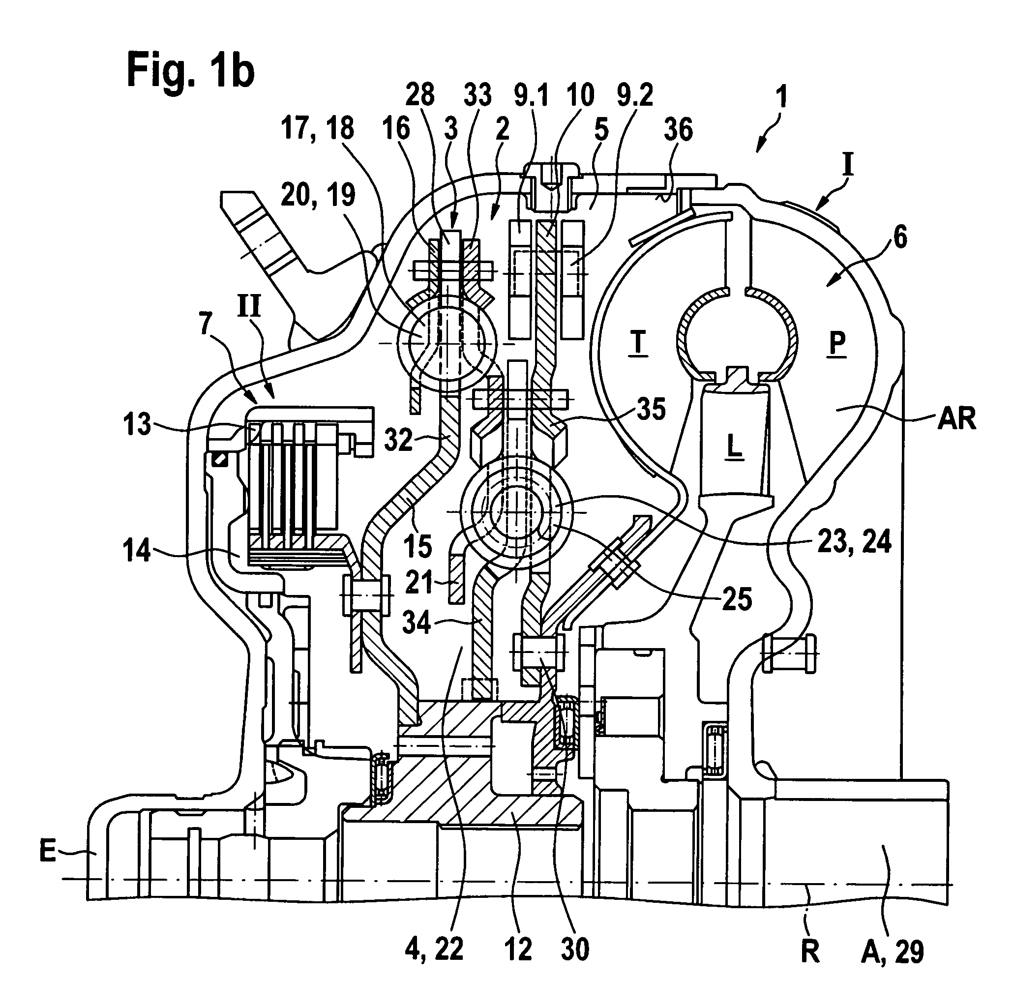
[0025]FIG. 1a illustrates the basic configuration of a force transmission device 1 configured according to the invention for power transmission in drive trains, in particular in drive trains for vehicles in a simplified schematic view. Thus, the force transmission device 1 is used for power transmission between a drive engine 100 which can be configured e.g. as a combustion engine and an output 101. The force transmission device 1 thus comprises at least one input E and at least one output A. The input E is thus connected to the drive engine 100 at least indirectly. The output A is connected at least indirectly with the units 101 to be driven e.g. configured as a transmission. “At least indirectly” thus means that the coupling can either be performed directly, this means without additional transmission elements disposed there between, or indirectly through additional transmission elements. The terms “input” and “output” are to be interpreted from a functional point of view in force ...


PUM


Abstract

The invention relates to a force transmission device for power transmission between an input and an output, comprising at least an input and an output, and a vibration damping device disposed in a cavity that can be filled at least partially with an operating medium, in particular oil, the vibration damping device coupled with a rotational speed adaptive absorber, wherein the rotational speed adaptive absorber is tuned as a function of an oil influence to an effective order qeff, which is greater by an order shift value qF than an order q of an exciting vibration of a drive system.

Description

RELATED APPLICATIONS[0001]This patent application is a continuation of International patent application PCT / DE 2008 / 001901 filed on Nov. 17, 2008 claiming priority from and incorporating by reference German patent application DE 10 2007 057 447.0, filed on Nov. 29, 2007.FIELD OF THE INVENTION[0002]The invention relates to a force transmission device, in particular for power transmission between a drive engine and an output, the device including a hydrodynamic component and a vibration damping device with a rotational speed adaptive absorber. The invention furthermore relates to a method for improving the damping properties of such force transmission devices.[0003]Force transmission devices in drive trains between a drive engine and an output are known in the art in various configurations. When an internal combustion engine is used as a drive engine, a rotation occurs at the crankshaft, which superimposes the rotating motion, wherein the frequency of the rotation changes with the rot...

Claims


Application Information

Patent Timeline
24 Apr 2012
Publication
US8161740B2
IPC
F16D43/18; F16F15/14
CPC
F16F15/145; F16F15/167; F16H2045/021; F16H2045/0263; F16H2045/0284
Inventors
KRAUSE, THORSTEN; ENGELMANN, DOMINIQUE