
Torque limiter

a torque limiter and torque limiter technology, applied in the direction of wrenches, screwdrivers, manufacturing tools, etc., can solve the problems of reducing the clearance tolerance, and clogging the body, so as to achieve quick tightening

Active Publication Date: 2012-04-24
STARK MICHAEL CURT WALTER
View PDF3 Cites 10 Cited by
  • Summary
  • Abstract
  • Description
  • Claims
  • Application Information

AI Technical Summary

Benefits of technology

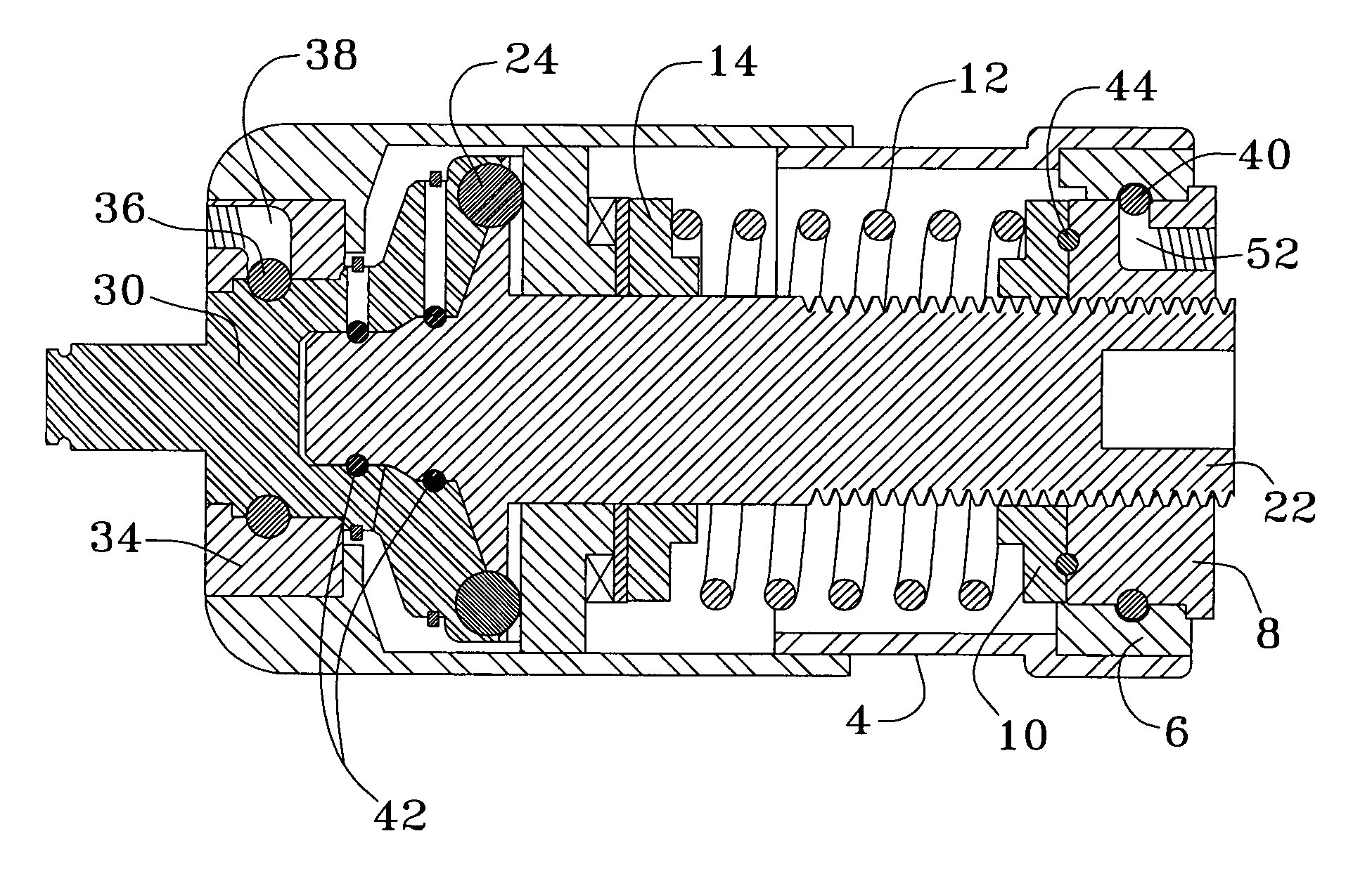
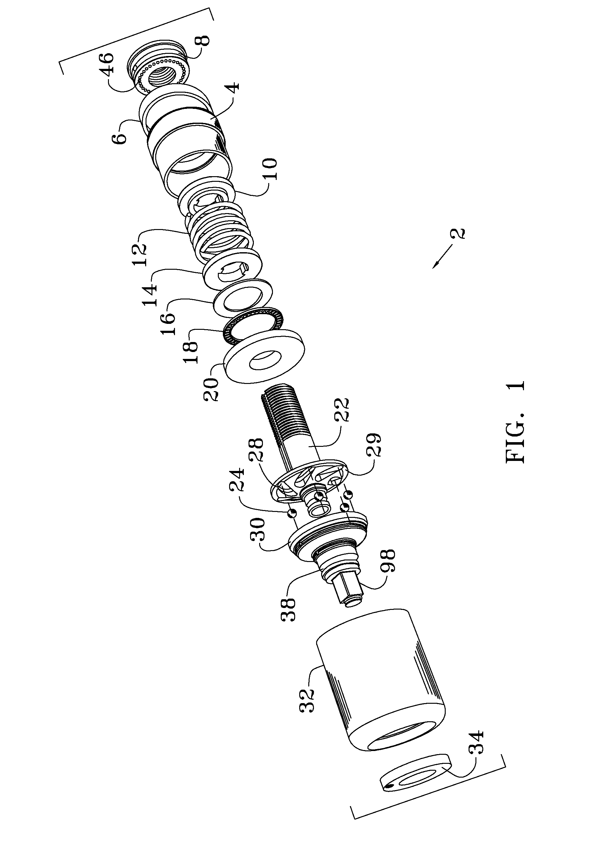
"The present invention provides an improved adjustable torque limiter that can be used with a variety of high-speed drivers. It can connect between a conventional mechanical driver and a conventional mechanical fastener bit. It can eliminate torque in excess of a desired preset value from being transmitted from a driver to the driven mechanical fastener. It is simple to calibrate and inexpensive. Overall, the invention solves problems of the prior art and provides a failsafe method of quickly tightening mechanical fasteners in a production environment to a specified torque value."

Problems solved by technology

Over tightening of mechanical fasteners can lead to cracked bodies, stretched and weakened bolts, stripped threads, smaller clearance tolerances, and a plethora of other maladies that can seriously affect the operation of the item in question.
Similarly, under tightening of mechanical fasteners can have its own, different but potentially disastrous results.
This slows the assembly process as conventional torque limiting devices require time to operate.
Further, many of the conventional torque limiting devices (such as a torque wrench) indicate the torque level yet do not prevent that level from being exceeded.

Method used


Image

  • Torque limiter
  • Torque limiter
  • Torque limiter

Examples


Embodiment Construction

[0065]There has thus been outlined, rather broadly, the more important features of the invention in order that the detailed description thereof that follows may be better understood and in order that the present contribution to the art may be better appreciated.

[0066]There are, of course, additional features of the invention that will be described hereinafter and which will form the subject matter of the claims appended hereto. In this respect, before explaining at least one embodiment of the invention in detail, it is to be understood that the invention is not limited in its application to the details of construction and to the arrangements of the components set forth in the following description or illustrated in the drawings. The invention is capable of other embodiments and of being practiced and carried out in various ways. Also, it is to be understood that the phraseology and terminology employed herein are for the purpose of descriptions and should not be regarded as limiting...


PUM

PropertyMeasurementUnit
torqueaaaaaaaaaa
speedaaaaaaaaaa
timeaaaaaaaaaa

Abstract

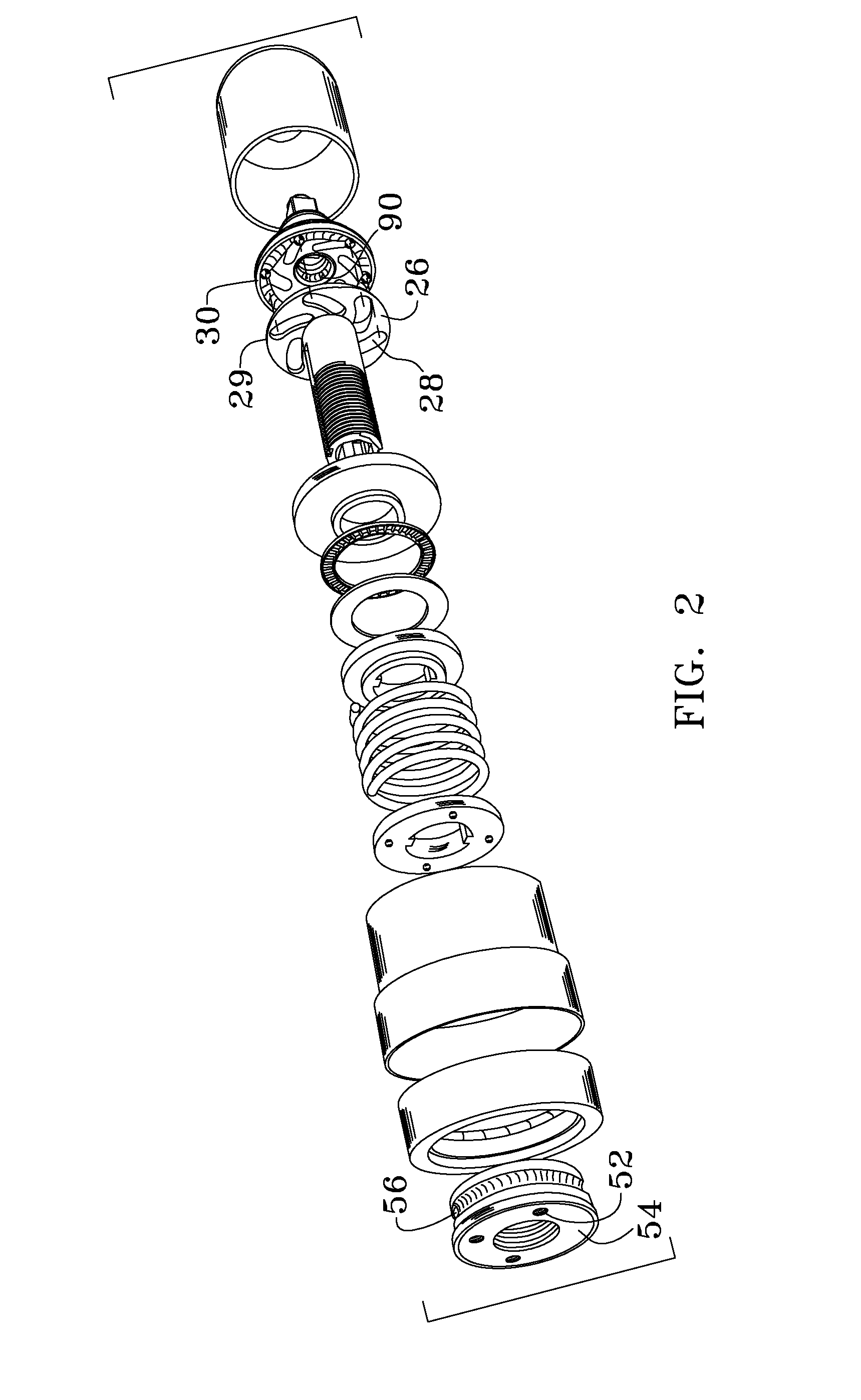
An adjustable torque limiter that can be coupled between a high speed driver and the socket that rotates a mechanical fastener. When a preset torque level is reached, the torque limiter disengages the rotational drive force from the bit. The adjustability of the torque limitation is accomplished by varying the amount of spring force by which a thrust plate (coupled to the high speed driver) is forced against a set of steel balls residing in slots of a radial torque plate and in a set of paths formed in a concavity of an upper torque body (coupled to the driven socket engaging stud). When a certain preset torque is transmitted from the driver to the socket, the steel balls traverse outward along the separate arced ramp radial paths therein the upper torque body until the balls enter an annular race that allows the thrust plate to go into a disengaged or free wheel mode from the upper torque body.

Description

BACKGROUND OF THE INVENTION[0001]The present invention relates to a extremely sturdy and versatile torque limiting device adapted to be used in conjunction with any type of driver tool utilized for the rotational tightening of mechanical fasteners. More particularly, to an accurate torque limiting device designed to be used in a production environment where the driver it is matingly coupled to is operated pneumatically, hydraulicly or electrically at a high speed.[0002]The proper operation of many mechanical components is, to a large degree, dictated by how the parts are assembled. Over tightening of mechanical fasteners can lead to cracked bodies, stretched and weakened bolts, stripped threads, smaller clearance tolerances, and a plethora of other maladies that can seriously affect the operation of the item in question. Similarly, under tightening of mechanical fasteners can have its own, different but potentially disastrous results. For this reason, where the tightness of a mechan...

Claims


Application Information

Patent Timeline
Patent Type & Authority Patents(United States)
IPC IPC(8): B25B23/157
CPCB25B23/141B25B23/1427Y10T408/70
Inventor STARK, MICHAEL CURT WALTER
Owner STARK MICHAEL CURT WALTER
Learn More