Bogie structure for a track vehicle

a track vehicle and bogie technology, applied in the direction of locomotives, rope railways, transportation and packaging, etc., can solve the problems of increasing weight, occupying a wide space, and affecting the maintenance of the vehicle, and achieve the effect of enhancing the maintenanceability and high speed

Inactive Publication Date: 2012-04-24
MITSUBISHI HEAVY IND LTD
View PDF26 Cites 15 Cited by
  • Summary
  • Abstract
  • Description
  • Claims
  • Application Information

AI Technical Summary

Benefits of technology

[0019]Thus, the present invention is devised in view of the above-mentioned background, and an object of the present invention is to provide a structure of a bogie for a vehicle in a track transportation system of the so-called center guide type with a new guide wheel mechanism, which includes guide wheels traveling along a guide rail laid on a track so as to allow the vehicle to run along a predetermined track path, and which can be simplified and is lightweight while it can run at a high speed with enhanced maintainability.

Problems solved by technology

However, the structure of the bogie of the side guide type track vehicle, as disclosed in the Japanese Patent Laid-Open No. 59-11955, requires extra components such as the guide beams 040 which are mounted at their both ends with the guide wheels 042, 042 and are extended left and right, and the two left and right arms 044 for pivotally supporting the guide beam 040, and further, the these components are heavy, resulting in an increase in the weight, and as well, are also bulky, resulting in a problem of occupation of a wide space.
Further, since they are bulky and heavy, the maintainability thereof are problematic.
Further, the center guide type as disclosed in the Japanese Patent Laid-Open No. 2002-019603 only has a limited space between the lower part of the vehicle and the running surface, in which required mechanisms including guide wheels should be accommodated.

Method used


Image

  • Bogie structure for a track vehicle
  • Bogie structure for a track vehicle
  • Bogie structure for a track vehicle

Examples


first embodiment

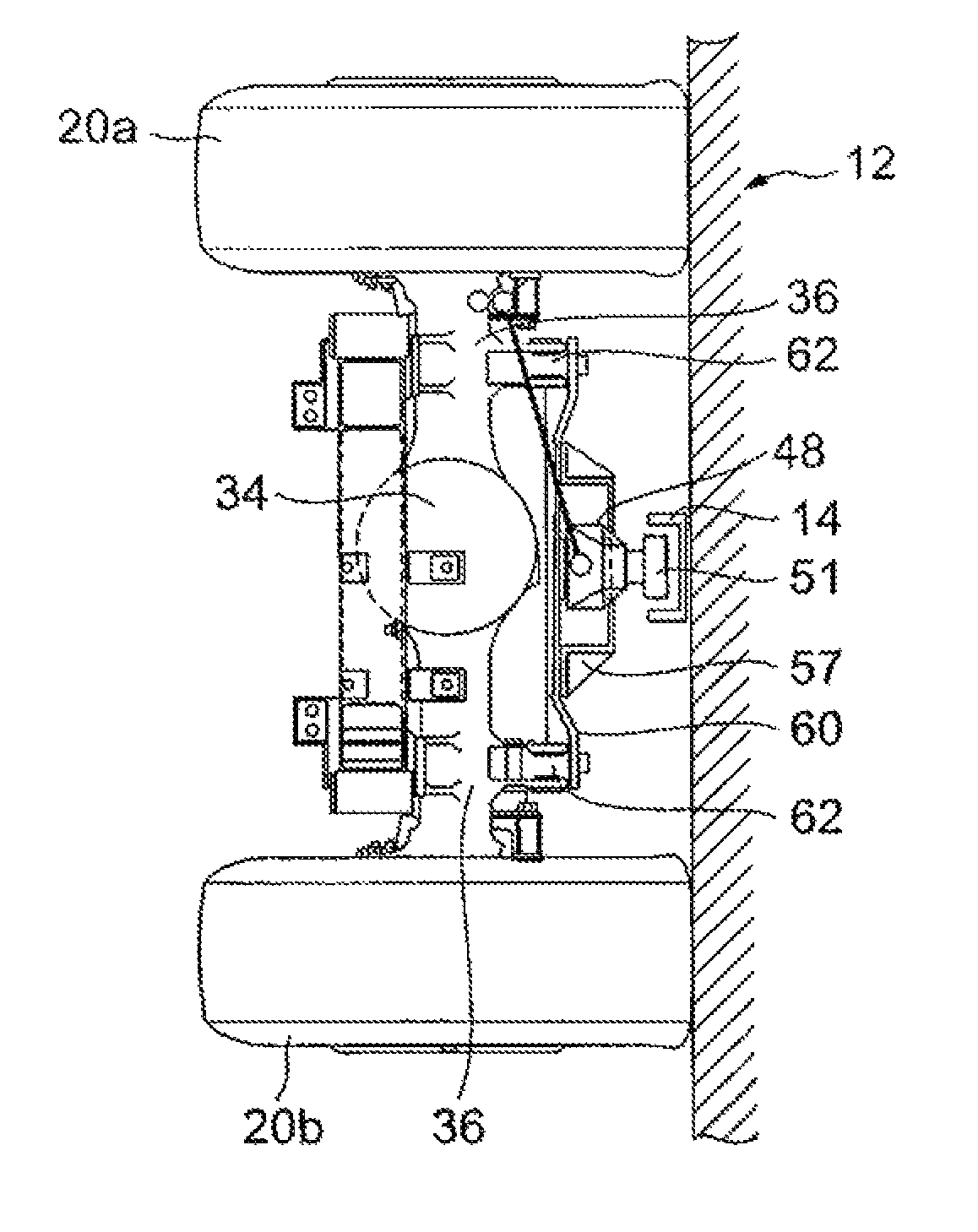
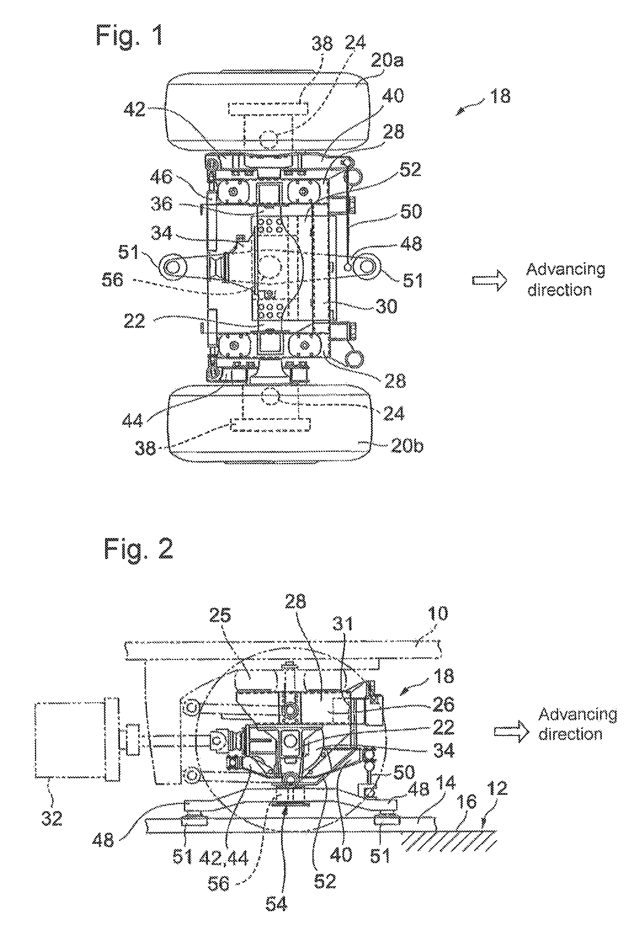
[0057]FIGS. 1 to 3 show a first embodiment of the present invention. A vehicle 10 used in a track type transportation system incorporates four wheels per vehicle, and runs along a track 12. A U-like cross-sectional shape guide rail 14 is laid in a substantially center zone of the track 12 in a groove-like manner with respect to a road surface 16. The U-like guide rail 14 is formed by laying a U-like steel bar on the road surface 6.

[0058]A bogie structure 18 shown in FIGS. 1 to 3, which is arranged in each of the front and rear portion of the vehicle 10, incorporates left and right front wheels 20a, 20b of a rubber tire type. The bogie structure on the front wheel side is similar to that on the rear wheel side, and accordingly, the bogie structure 18 which is located in the front part of the vehicle will be explained hereinbelow.

[0059]As shown in FIG. 1, the front left and right wheels 20a, 20b are mounted respectively to opposite end parts of an axle 22 which is extended left and ri...

second embodiment

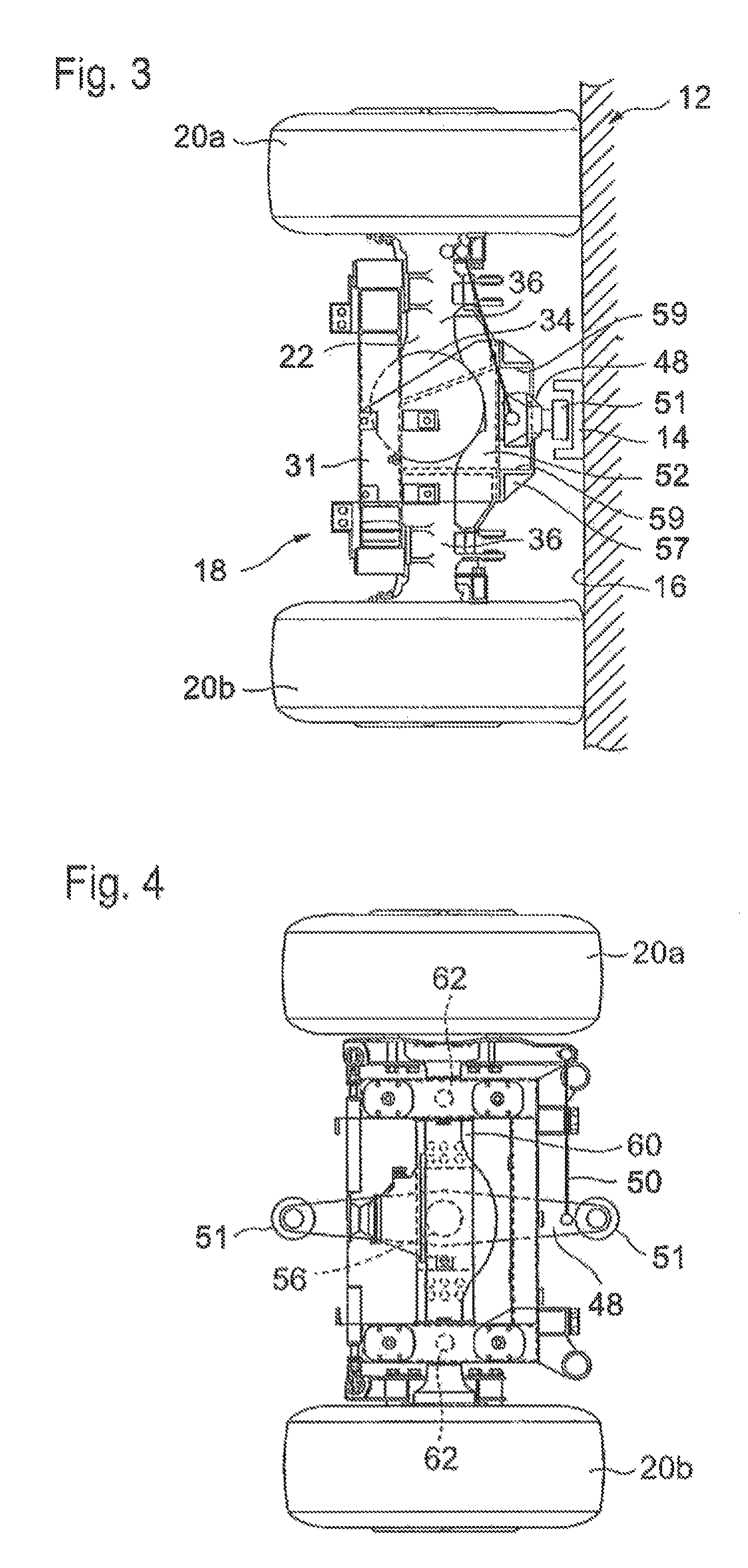
[0076]Next, explanation will be made of a second embodiment of the present invention with reference to FIGS. 4 to 6. The second embodiment will concerns a variant form of the guide wheel support bracket 52 in the first embodiment, and like reference numerals are used to denote like parts to those explained in the first embodiment so as to abbreviate the explanation thereto.

[0077]As shown in FIG. 5 which is a side view, similar to the first embodiment, the guide arm 48 which is located with its rotating center on the center axial line of the axle 22, is attached to the guide wheel support bracket 60 supported underneath the differential mechanism portion 34, and the guide wheel support bracket 60 is laid below the axle 22 along the direction of the axle, as shown in FIG. 6, and are attached, being bolted or welded, at its opposite ends to axle support seats 62, 62 provided in the axle body portion 36. Further, similar to the first embodiment, the structure of the arm member rotating ...

third embodiment

[0082]Next, explanation will be made of a third embodiment of the present invention with reference to FIGS. 7 to 9. The third embodiment will concern a variant form of the guide wheel support bracket 60 in the second embodiment, and like reference numerals are used to denote like parts to those explained the second embodiment so as to abbreviate the explanation thereto.

[0083]Referring to FIG. 8 which is a side view and FIG. 9 which is a front view, the structure of an arm rotating and supporting part 72 incorporated in a guide wheel support bracket 70 has not the both end support configuration but has a cantilever configuration. That is, the pivotal support shaft 56 is not supported up and down, but is supported only by the guide wheel support bracket 70 in the cantilever configuration using a component corresponding to the protection frame 57 explained in the second embodiment.

[0084]With this third embodiment, the pivot support shaft 56 can be supported without using a component co...


PUM


Abstract

The present invention provides the structure of a bogie for a vehicle in a track type transportation system in which the vehicle runs along a predetermined track, which can be simplified, and lightweight and which can be run at a high speed with the maintainability therefor being enhanced, comprising a guide rail 14 laid on the track 12, guide wheels 51 capable of traveling being made into contact with the guide rail 14, a guide arm 48 attached thereto with the guide wheels 51, and a guide wheel support bracket 52 for supporting the guide arm 48 arranged underneath an axle 22 of the vehicle so that the guide arm 48 is pivotable around a pivotal vertical support shat 56, left and right of the vehicle, and the guide arm 48, the guide wheels 51 and the guide wheel support bracket 52 constitute a unit structure which is attached to the axle 22 or a bogie frame 26 of the vehicle.

Description

CROSS-REFERENCE TO RELATED APPLICATIONS[0001]The present application is based on International Application No. PCT / JP2006 / 323371, filed on Nov. 16, 2006, and priority is hereby claimed under 35 USC §119 based on this application. This application is hereby incorporated by reference in its entirety into the present application.TECHNICAL FIELD[0002]The present invention relates to a bogie structure for a track type vehicle which runs on a predetermined track by means of, for example, rubber tire type running wheels.BACKGROUND ART[0003]Different from a railway vehicle running on rails, a vehicle in a new transportation system in which a vehicle body runs being carried by rubber tires driven under rotation, is normally provided with steering guide wheels making contact with a guide rail laid along the track, for turning the rubber tires serving as running wheels, along a predetermined track, that is, the vehicle runs being mechanically steered.[0004]As the guide rail, there have been pr...

Claims


Application Information

Patent Timeline
Patent Type & Authority Patents(United States)
IPC IPC(8): B61F9/00
CPCB61F9/00B62D1/265B61B13/00B61F5/38B62D1/26G05D1/02
Inventor MORICHIKA, SHUNJIMORITA, KATSUAKIKONO, HIROYUKIMOCHIDOME, HIROYUKIYAMASHITA, HIROSHIYAMAGUCHI, MASAHIROKATAHIRA, KOSUKE
Owner MITSUBISHI HEAVY IND LTD
Why Eureka
Try Eureka