Elevator having a limit switch for controlling power to the drive system as an elevator car approaches a shallow pit or a low overhead

a technology of limit switch and drive system, which is applied in the direction of elevators, building lifts, transportation and packaging, etc., can solve the problems of preventing the car from moving further up, reducing the speed of the elevator, and wasting time in movement, so as to achieve a simple and safe arrangement

Inactive Publication Date: 2012-04-24
OTIS ELEVATOR CO
View PDF37 Cites 21 Cited by
  • Summary
  • Abstract
  • Description
  • Claims
  • Application Information

AI Technical Summary

Benefits of technology

[0008]at least one limit switch which is open when the car is in a selected distance range from one of the end positions, the limit switch forming part of a power line supplying power to the drive system for controlling movement of the car in a direction towards said one of the end positions in an inspection operation such that movement of the car is prevented only in said direction when the car is in said distance range in an inspection operation.
[0011]This embodiment thus provides an inspection operation which is both safe and efficient.
[0019]Handrails are used on top of elevator cars to avoid hazards for people standing there. They must be foldable in low overhead configurations so as to occupy a very limited height, e.g. less than 10 cm. Examples of such foldable handrail arrangements are disclosed in WO 2005 / 026033 and WO 2005 / 105645. The above embodiment of the invention secures the right positioning of the handrail while the car is moving both in normal elevator operation and in inspection operation.
[0027]An elevator toe guard extends downwardly from the lower front sill of an elevator car. The toe guard is an important safety feature since it provides a barrier between a landing and the hoistway when the car is not aligned with the landing. For example should the car become trapped between floors, the toe guard reduces the danger of a person attempting to rescue the passengers, or the passengers themselves, falling into the hoistway. Regulations and good safety practice dictate a minimum height for toe guards. Clearly in order to accommodate such a toe guard fixed to the bottom of an elevator car, the pit must be sufficiently deep that the toe guard will not strike the bottom of the pit even if the elevator travels below the lowest landing and onto the buffers. As this condition is not always fulfilled in shallow pit elevators, retractable toe guards have been proposed. An example is disclosed in WO 2005 / 092774. Such a toe guards retracts when it contacts the bottom of the pit while the car reaches the lowest landing level in normal operation. The switch associated with the toe guard in this aspect of the invention make it possible to check that the toe guard does not become jammed in a retracted position, or in a not fully deployed position, prior to enabling normal operation of the elevator, thus guaranteeing the safety feature of the toe guard.
[0035]This provides a simple and safe arrangement of an intrusion detector for the shaft. Movement of the car is inhibited once the mechanic has released a landing door to access the shaft. Then, an inspection travel can be performed if the mechanic actuates the mode switch from inside the shaft (the car roof or the pit). When the elevator is brought back to the normal mode of operation, the car is only permitted to move after the mechanic has checked out of the shaft by performing the second action on the safety device of the door by which he came in.

Problems solved by technology

He usually wishes the car to stop at a position where he can clamber on top of it without having to move the car too long afterwards to reach the desired working position (in the inspection mode, the car speed is much reduced compared to the normal mode and such movement can be a waste of time).
But this is tricky because most of the time the car cannot be seen by the mechanic and the distance needed for the brake to effectively stop the car must be taken into consideration.
A bad aim can cause the car to stop just above the limit switch, and the mechanic may not wish to spend time in the procedure for closing the door, bringing the elevator back into the safe normal mode and trying again.
Of course, safety provided by the limit switch precludes the car to move further up in such circumstances.

Method used


Image

  • Elevator having a limit switch for controlling power to the drive system as an elevator car approaches a shallow pit or a low overhead
  • Elevator having a limit switch for controlling power to the drive system as an elevator car approaches a shallow pit or a low overhead
  • Elevator having a limit switch for controlling power to the drive system as an elevator car approaches a shallow pit or a low overhead

Examples


Embodiment Construction

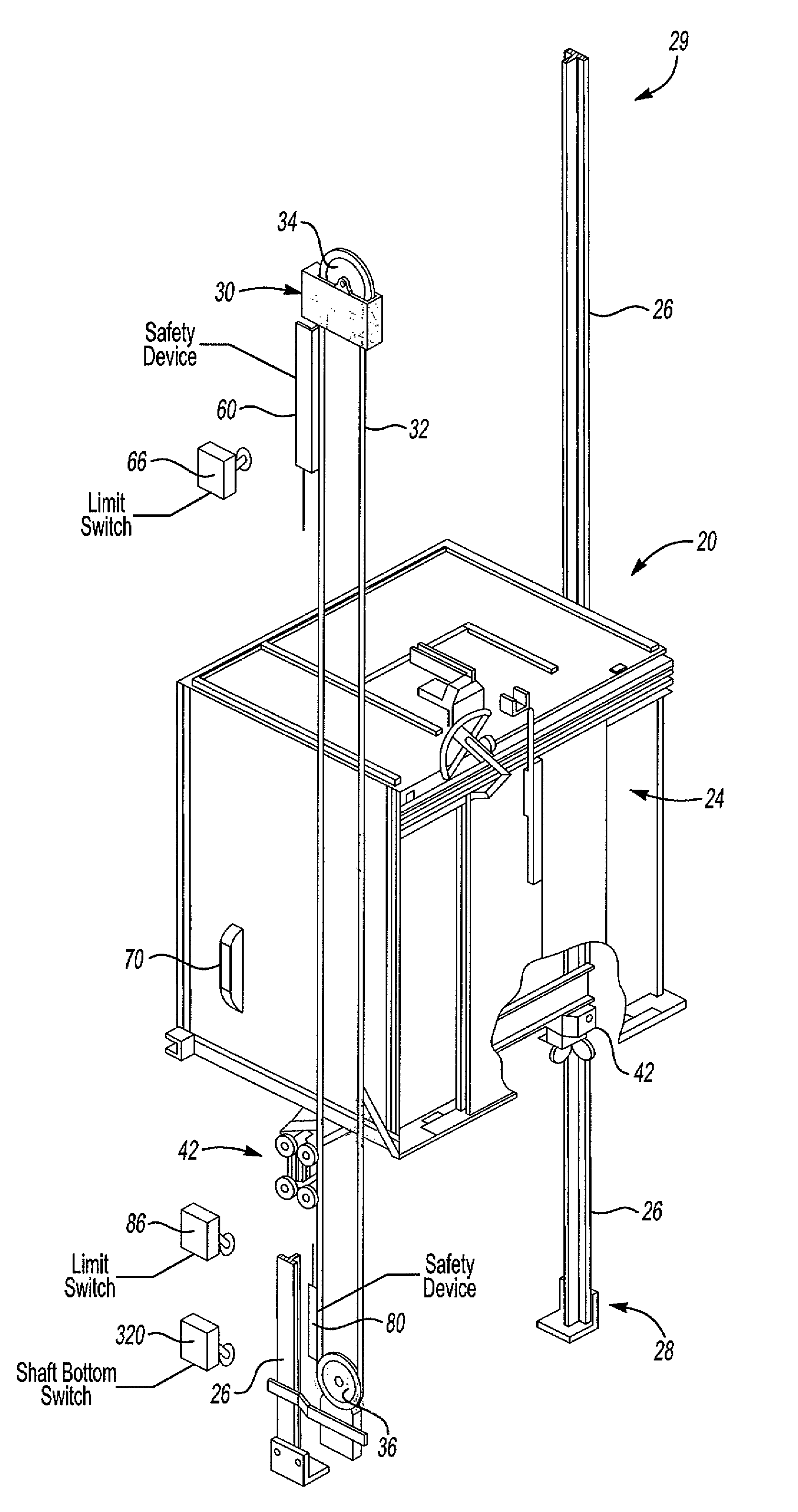
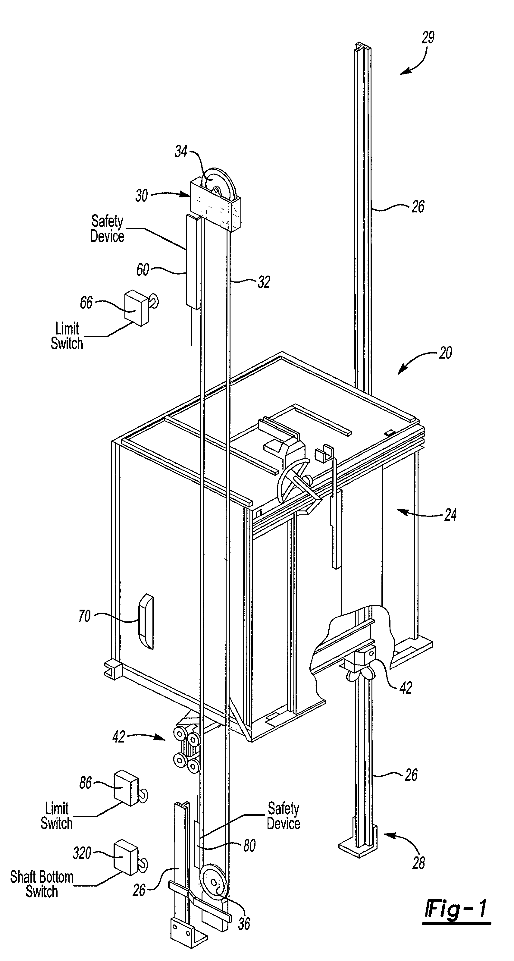
[0045]FIG. 1 shows an elevator system 20 including an elevator car 24 that moves along guide rails 26 in a known manner.

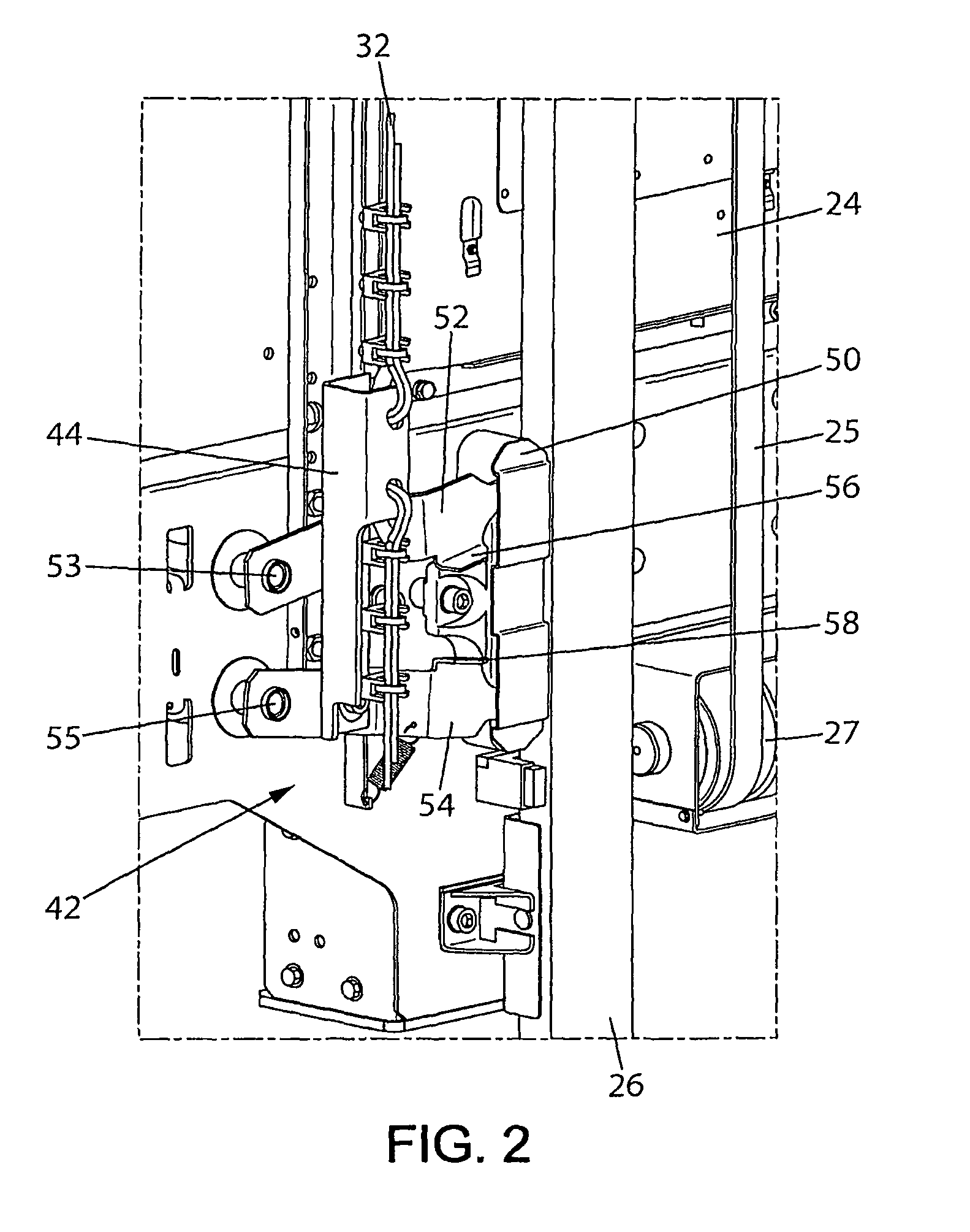
[0046]In one example, a machine room-less elevator system allows the car 24 to move essentially along the entire length of a hoistway between a lower end 28 (i.e. a pit) and an upper end 29 of a hoistway. A drive system (not shown) including a motor and a brake is conventionally used to control the vertical movements of the car 24 along the hoistway via a traction system partly visible in FIG. 2, including cables or belts 25 and reeving pulleys 27.

[0047]In addition, a governor device 30 controls movement of the car 24 by preventing it from moving beyond a selected maximum speed. The example governor device 30 includes a governor rope 32 that travels with the car 24 as the car moves along the guide rails 26. A governor sheave 34 and a tension sheave 36 are at opposite ends of a loop followed by the governor rope 32.

[0048]The illustrated governor device 30 operates i...


PUM


Abstract

The elevator has a car movable vertically within a shaft between lower and upper end positions and a drive system coupled to a traction system for controlling movement of the car. A limit switch which is open when the car is in a selected distance range from one of the end positions. The limit switch forms part of a power line supplying power to the drive system for controlling movement of the car in a direction towards that end position in an inspection operation. Thus movement of the car is prevented only in that direction when the car is in the selected distance range in an inspection operation.

Description

BACKGROUND OF THE INVENTION[0001]The present invention relates to elevators. It applies, in particular, to elevators having a shallow pit and / or a low overhead.[0002]Elevators with a shallow pit and / or a low overhead are advantageous because of the reduced impact of their installation on the construction cost and because of their compatibility with severe architectural constraints.[0003]Machine room-less elevators have their drive system, in particular their motor and brake, located inside the volume of the elevator shaft. Access to these parts, and to other components fitted in the shaft is required for maintenance or repair purposes. Standards such as EN81 require safety clearances at the top and at the bottom of the shaft so that a person can enter a safe working space to have access to the machines and shaft components. Such working space can be located in the upper part of the hoistway, with the operator standing on top of the car, or in the pit at the bottom of the shaft.[0004...

Claims


Application Information

Patent Timeline
Patent Type & Authority Patents(United States)
IPC IPC(8): B66B1/06
CPCB66B5/0068B66B5/0081B66B5/18B66B13/16B66B13/22B66B5/0087
Inventor SIRIGU, GERARDREBILLARD, PASCALDUKACZ, OLIVIERGOULET, DOMINIQUESIMONOT, ALAINCLOUX, JEAN-NOELPILLIN, DAVIDPICARD, FLORENCEBEAUCHAUD, FREDERICCOQUERELLE, THOMASBEEUWSAERT, MICHELFONTENEAU, NICOLASMONZON, ANDRESDEL RIO, FERNANDOHERKEL, PETERTEGTMEIER, DIRK
Owner OTIS ELEVATOR CO
Why Eureka
Try Eureka