Method for controlling the discharge pressure of an engine-driven pump

a technology of engine-driven pumps and discharge pressure, which is applied in the direction of electric control, positive displacement liquid engines, speed sensing governors, etc., can solve the problems of extreme danger, changes, and surges or oscillations in water flow discharge at the nozzle, and achieve the effect of only functioning relief valves

Active Publication Date: 2012-04-24
HALE PROD INC
View PDF9 Cites 12 Cited by
  • Summary
  • Abstract
  • Description
  • Claims
  • Application Information

AI Technical Summary

Problems solved by technology

This is problematic because even slight variations in pressure in the supply line leading to the intake of the pump are amplified by the pump on the discharge side, causing surges or oscillations in the water flow discharge at the nozzle and corresponding changes in the reaction forces.
Such changes are extremely dangerous, as they can pull a nozzle out of the fireman's grip, or even throw him or her off a ladder or ledge.
A shortcoming of such a valve, however, is that, the relief valve only functions to dissipate excess pressure, and has no utility in situations where the pressure is too low, such as when the water source is being depleted or another hose is connected to the system.
In addition, if the pump engine continues to operate at full speed after the relief valve is opened, water will be continuously recirculated in the system, resulting in needless waste and wear and tear on the pump and engine.
Overheating of the pump and engine is also more likely.
A shortcoming of this type of system is that, because the response time of the servo-mechanism controlling the engine is slow, much time can pass before the appropriate rpm and correct discharge pressure are reached.
This is especially troublesome during transient events, such as overpressure spikes, where the system's response time is greater than the length of the event.
Furthermore, no allowance is made for situations such as when the engine is already at idle and the incoming pressure suddenly increases, or is higher than desired, such as what can happen when the pump is connected to a hydrant.
The shortcomings of this system are that the change in engine speed and the relief valve may be operated at the same time resulting in a waste of water.
In addition, operating the engine and relief valve simultaneously results in a needlessly complicated response system.

Method used


Image

  • Method for controlling the discharge pressure of an engine-driven pump
  • Method for controlling the discharge pressure of an engine-driven pump
  • Method for controlling the discharge pressure of an engine-driven pump

Examples


Embodiment Construction

[0014]Certain terminology is used in the following description for convenience only and is not limiting. The words, “right”, “left”, “up”, “down”, “top”, and “bottom” designate directions in the drawings to which reference is made. The words “interior” and “exterior” refer to directions toward and away from, respectively, the geometric center of the pump system or parts or portions thereof. Furthermore, as used herein, the article, “a” or singular components include the plural or more than one component, unless specifically and explicitly restricted to the singular or a singular component or unless a singular meaning is apparent from the context. The terminology includes the words above specifically mentioned, derivatives thereof and words of similar meaning.

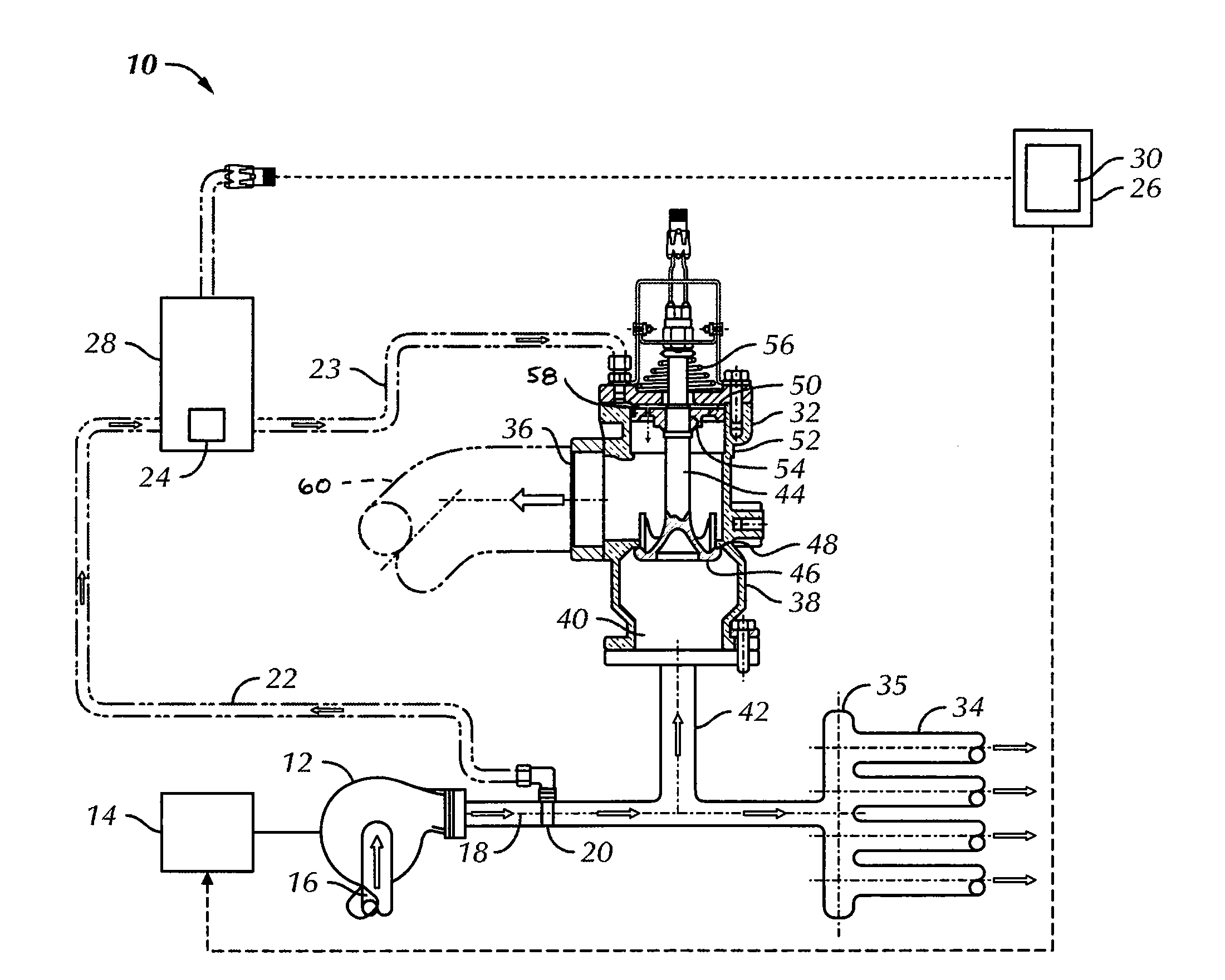
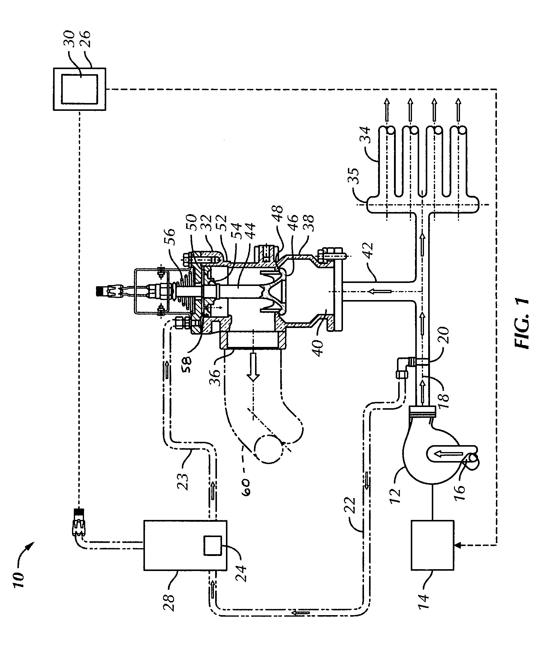
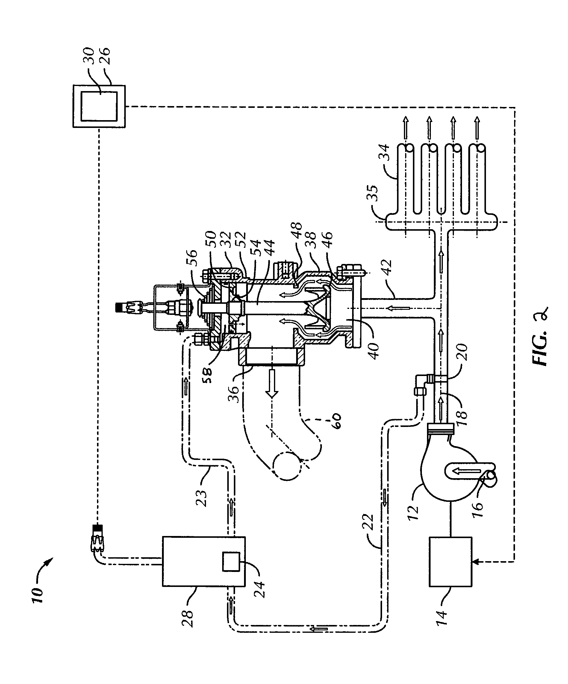
[0015]Referring to the drawings in detail, wherein like reference numerals are used to identify like components throughout, there is shown in FIGS. 1-3, the preferred embodiment of a system, generally designated 10, for controll...


PUM


Abstract

A system for controlling the pressure output of an engine-driven centrifugal fire pump includes a discharge pressure sensor mounted in the discharge line of the pump. A governor varies the rpms of the engine in response to pressure changes detected by the discharge pressure sensor. If the pressure in the system is higher than the desired output pressure when the engine is running at its idle speed an electronically controlled hydraulic relief valve responsive to the discharge pressure sensor operates to relieve the excess pressure in over pressure situations. If the pressure in the system is lower than the desired output pressure when the relief valve is fully closed, the engine speed is increased.

Description

BACKGROUND OF THE INVENTION[0001]This invention relates to a method for controlling the pressure output of an engine-driven pump system. Specifically, this invention relates to a method of controlling the discharge pressure of an engine-driven pump for use in a fire truck.[0002]It is vital to control the discharge pressure of an engine-driven fire pump mounted on or in a fire truck. The pump must supply water at various rates and steady pressure so that firemen operating the hoses at a fire scene can control the reaction force generated by their hose nozzles. Fire pumps as used here are centrifugal pumps. These pumps add pressure to the incoming source of water. Therefore pressure changes in the supply are pressure changes in the discharge. This is problematic because even slight variations in pressure in the supply line leading to the intake of the pump are amplified by the pump on the discharge side, causing surges or oscillations in the water flow discharge at the nozzle and corr...

Claims


Application Information

Patent Timeline
Patent Type & Authority Patents(United States)
IPC IPC(8): F04B49/08F04B53/10F04B17/05F04B49/03
CPCF02D29/04F02D31/001F02D41/021F04B49/24F02D41/083Y10T137/777
Inventor LASKARIS, MICHAEL A.
Owner HALE PROD INC
Why Eureka
Try Eureka