High power receptacle connector

a high-power receptacle and connector technology, applied in the direction of coupling contact members, coupling device connections, coupling protective earth/shielding arrangements, etc., can solve the problem that conventional connectors cannot afford to transmit high-power signals, and achieve high-power, prevent power/signal transmission failure, and improve contact capability

Inactive Publication Date: 2012-04-24
JYE TAI PRECISION INDAL
View PDF26 Cites 47 Cited by
  • Summary
  • Abstract
  • Description
  • Claims
  • Application Information

AI Technical Summary

Benefits of technology

[0007]The main objective of the invention is to provide a high power receptacle connector that improves contacting capability with other connectors connected thereto and prevents power / signal transmission failure or unusual increase of the resistance. Therefore, high power signal transmission is achieved.
[0008]A high power receptacle connector in accordance with the present invention comprises a first insulating housing, a second insulating housing, a first terminal, a second terminal, a third terminal and a shell. The second insulating housing is mounted on the first insulating housing and has a cylinder. The first terminal is cylindrical, surrounds the cylinder and has multiple first resilient contacting tabs and a reinforcing ring formed on front ends of the first resilient contacting tabs. The second terminal is cylindrical and mounted around the cylinder and has multiple radially protruding second resilient contacting tabs. The second resilient contacting tabs increase the contacting areas, reduce the resistance of the terminals and further improve the power of the high power receptacle connector and stably hold an external plug connector.

Problems solved by technology

However, conventional connectors cannot afford transmission high power signals so that the connector manufacturers constantly develop new high power connectors.

Method used


Image

  • High power receptacle connector
  • High power receptacle connector
  • High power receptacle connector

Examples


Embodiment Construction

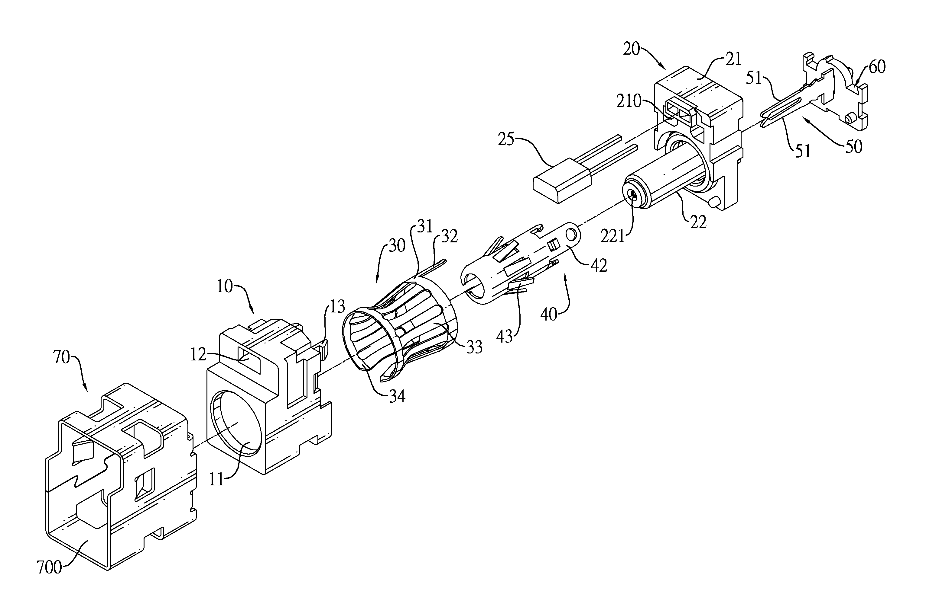
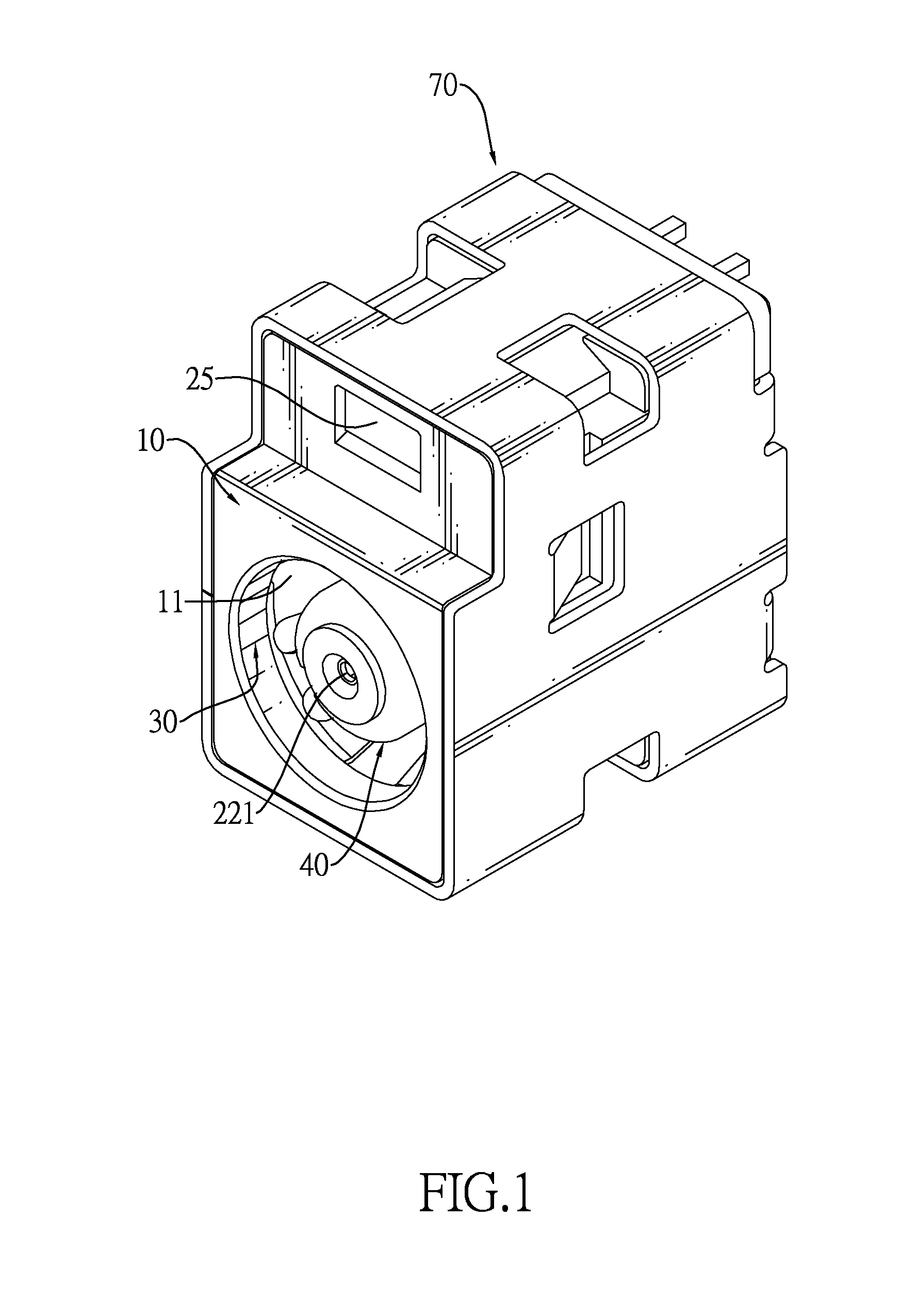
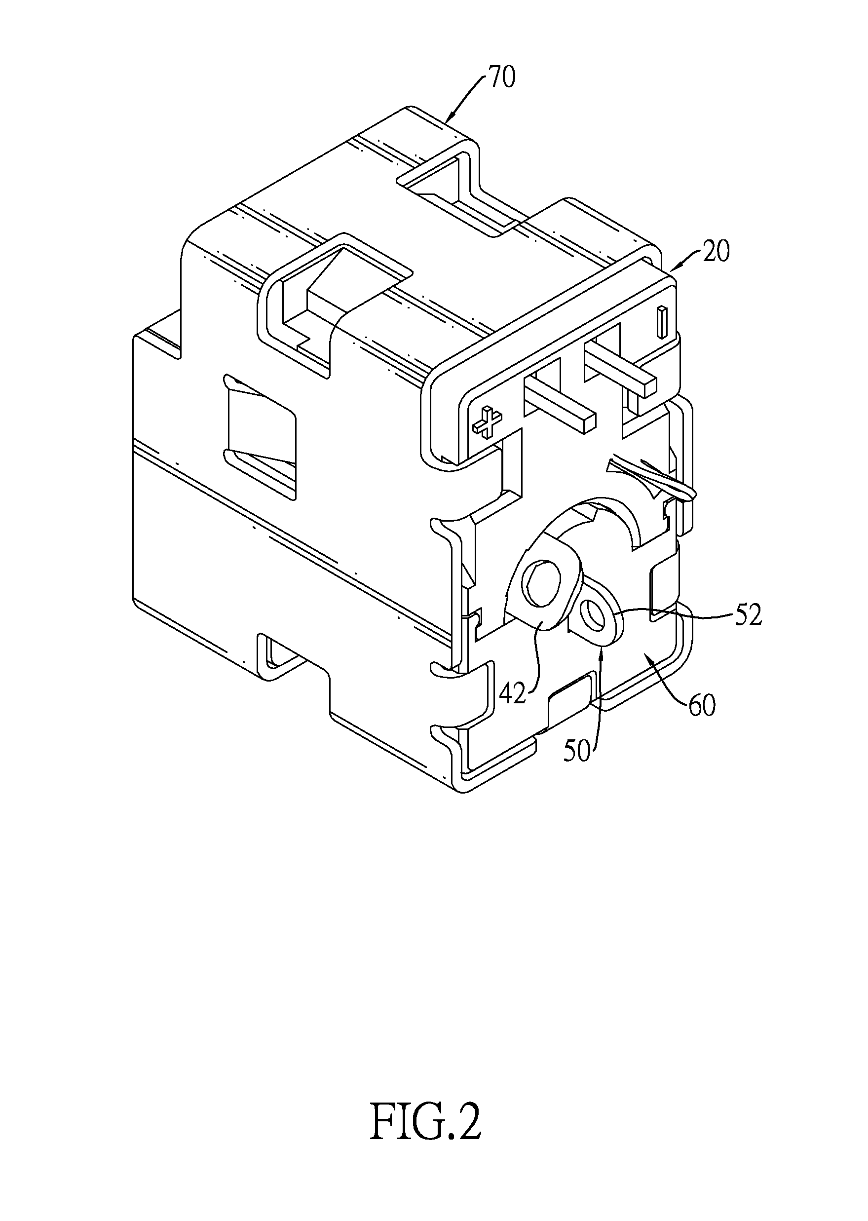
[0016]With reference to FIGS. 1 to 4, a high power receptacle connector in accordance with the present invention comprises a first insulating housing (10), a second insulating housing (20), a first terminal (30), a second terminal (40), a third terminal (50), a shell (70) and a mounting bracket (60).

[0017]The first insulating housing (10) has a front end, a rear end, a cavity (11), two hooks (13) and an assembling hole (12).

[0018]The cavity (11) is defined longitudinally through the first insulating housing (10).

[0019]The hooks (13) are formed on and protrude backward from the rear end of the first insulating housing (10).

[0020]The assembling hole (12) is defined longitudinally through the first insulating housing (10) above the cavity (11).

[0021]With further reference to FIGS. 5 and 6, the second insulating housing (20) is mounted on the rear end of the first insulating housing (10) and has a front end, a rear end, a base (21), a cylinder (22) and a light-emitting element (25).

[002...


PUM


Abstract

A high power receptacle connector has a first insulating housing, a second insulating housing, a first terminal, a second terminal, a third terminal and a shell. The second insulating housing is mounted on the first insulating housing and has a cylinder. The first terminal is cylindrical, surrounds the cylinder and has multiple first resilient contacting tabs and a reinforcing ring formed on front ends of the first resilient contacting tabs. The second terminal is cylindrical and mounted around the cylinder and has multiple radially protruding second resilient contacting tabs. The second resilient contacting tabs increase the contacting areas, reduce the resistance of the terminals and further improve the power of the high power receptacle connector and stably hold an external plug connector.

Description

BACKGROUND OF THE INVENTION[0001]1. Field of the Invention[0002]The present invention relates to a connector, and more particularly to a high power receptacle connector that improves contacting capability with other connectors connected to the high power receptacle connector and prevents power / signal transmission failure or unusual increase of the resistance. Therefore, high power signal transmission is achieved.[0003]2. Description of Related Art[0004]Connectors are common electrical components of electronic devices. Different electronic devices are connected to each other by connectors so that signal transmission is implemented between different electronic devices to further incorporate these electronic devices into a specific electronic system.[0005]The semiconductor industries are rapidly developed in recent years so that electronic devices have high-speed and high-performance built-in processing chips to fulfill user's demand. Also, the connectors of the electronic devices need...

Claims


Application Information

Patent Timeline
Patent Type & Authority Patents(United States)
IPC IPC(8): H01R12/00
CPCH01R13/11H01R24/38H01R2105/00
Inventor HUANG, FU-TANG
Owner JYE TAI PRECISION INDAL
Why Eureka
Try Eureka