Shock wave treatment device and method of use

a shock wave and treatment device technology, applied in the field of shock wave treatment devices and methods, can solve the problems of complex delivery of shock waves to internal organs, difficulty in treating such organs as the heart, cavitation effects,

a shock wave and treatment device technology, applied in the field of shock wave treatment devices and methods, can solve the problems of complex delivery of shock waves to internal organs, difficulty in treating such organs as the heart, cavitation effects,

US8162859B2Active Publication Date: 2012-04-24HEART REGENERATION TECH GMBH

Image

  • Shock wave treatment device and method of use
  • Shock wave treatment device and method of use
  • Shock wave treatment device and method of use

Examples


Embodiment Construction

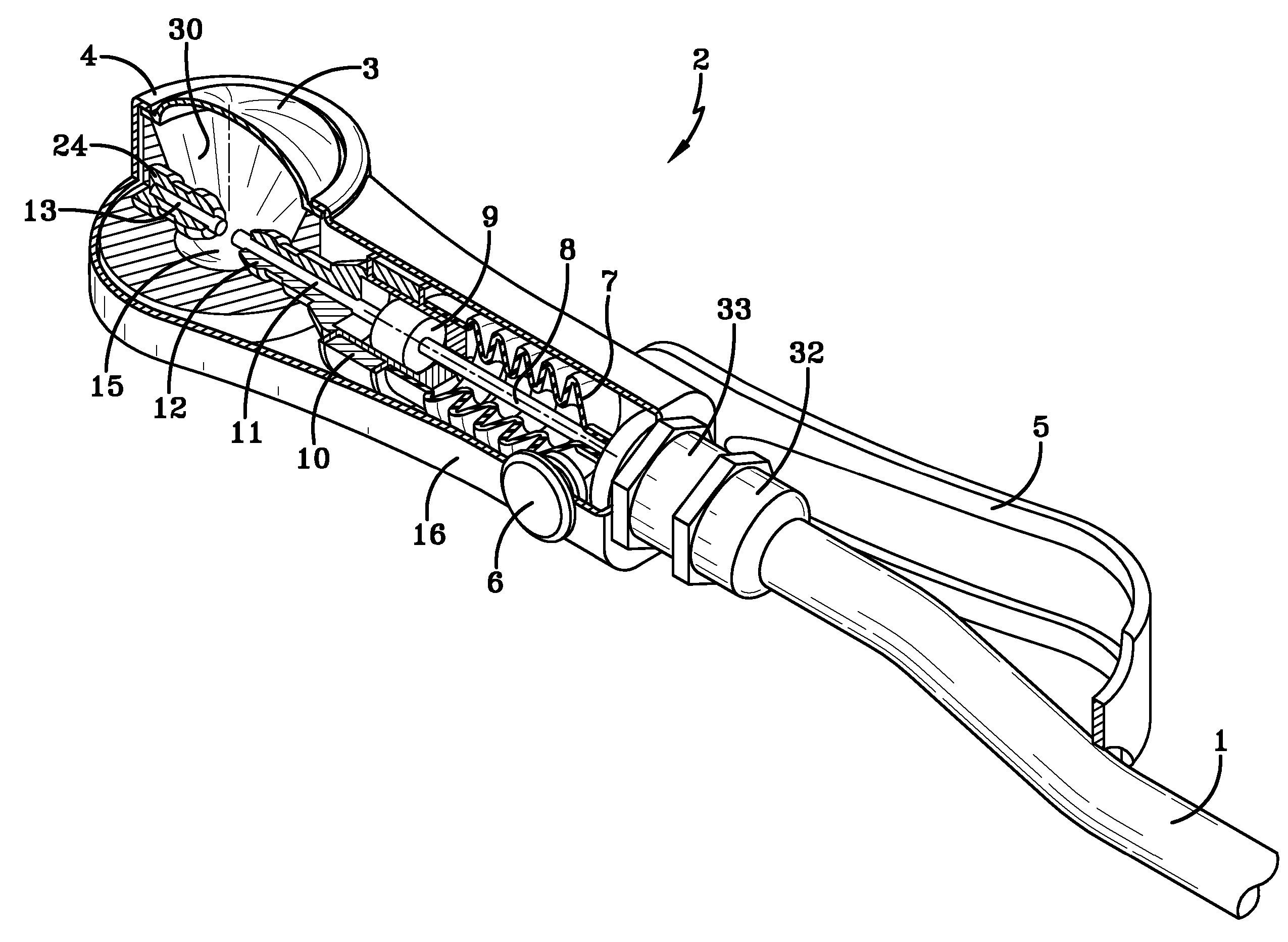
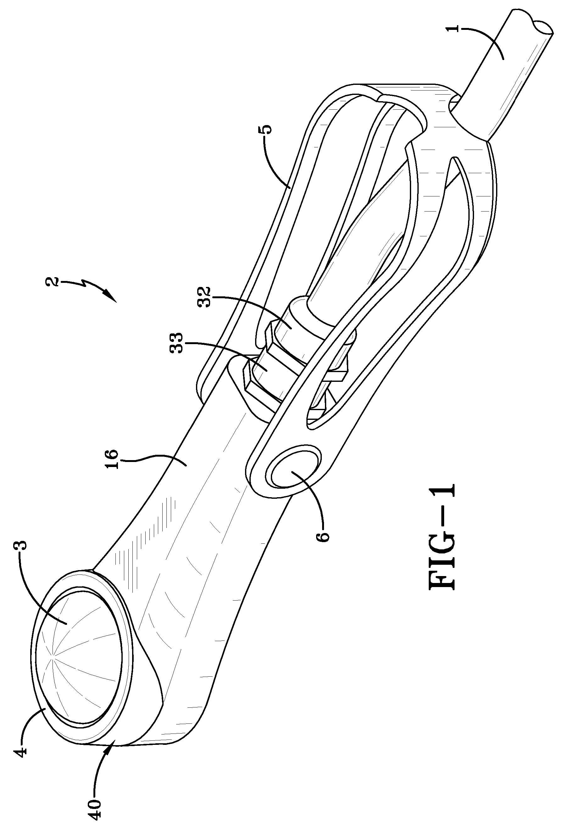
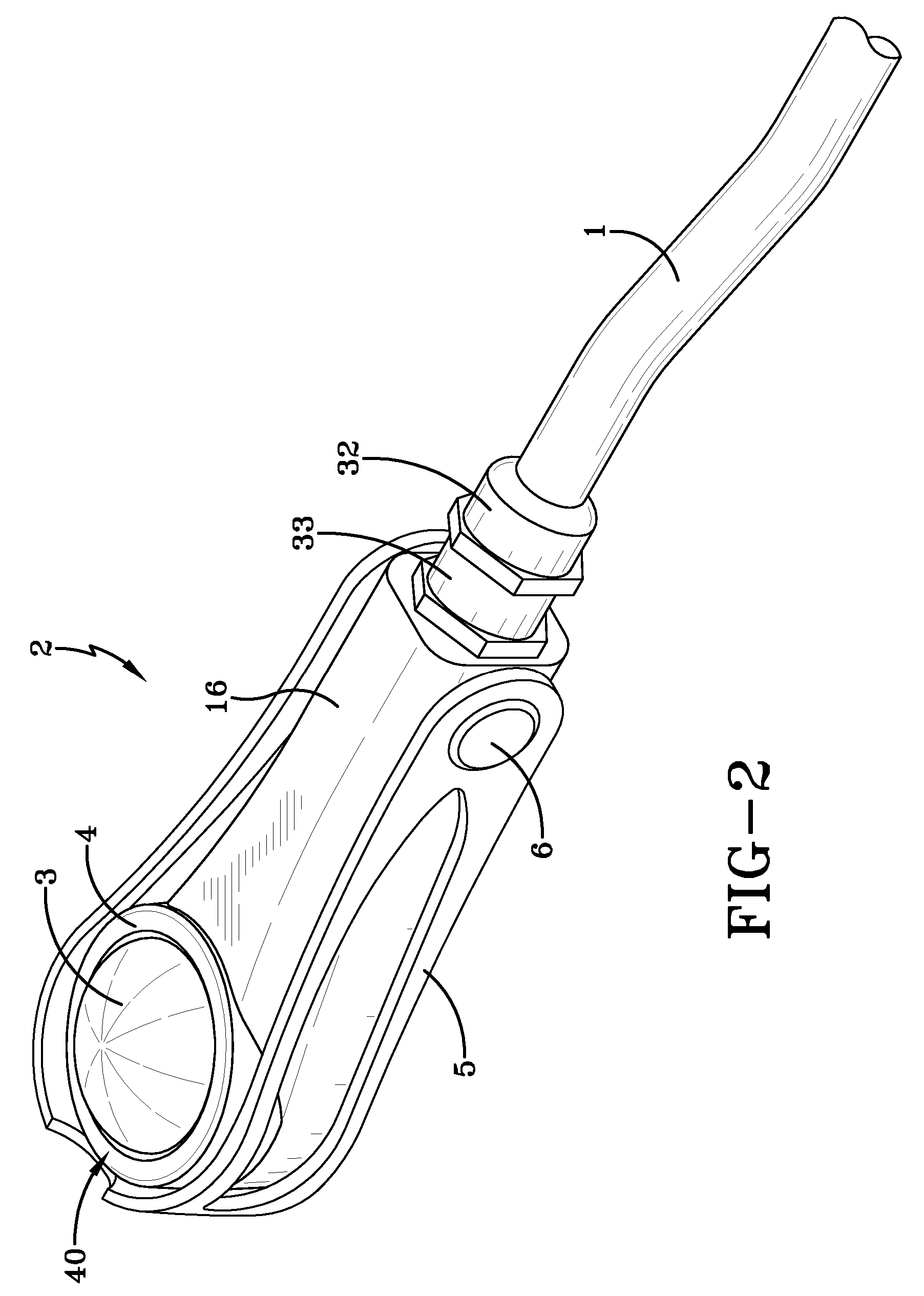
[0053]With reference to FIGS. 1 and 2 a small portable hand-held shock wave applicator device 2 is illustrated. The shock wave applicator 2 has a cable 1 extending from an end of an applicator housing 16. The cable 1 is connected to a shock wave generator (schematically illustrated in FIG. 12) and as illustrated in FIGS. 1 and 2 fastened to the applicator housing 16 via a pair of threaded connectors 32, 33.

[0054]At the opposite end of the applicator 2 is an applicator head portion 40 as shown the applicator head portion 40 has a rounded contour with a diameter of approximately 5 cm, preferably smaller which enables the device to be easily positioned around or under the organ to be treated. It is in this portion 40 that the shock wave patterns are produced, reflected and emitted to the organ or tissue 100 being treated. The head portion 40 includes an outer membrane 3 which is sealed and retained by the annular fixation ring 4 which secures and holds the membrane 3.

[0055]Attached to ...


PUM


Abstract

The system for treating an internal organ has a generator source for producing a shock wave connected to a portable shock wave applicator device, wherein the shock wave applicator device has a side-firing shock wave head having a variable angle adjustment relative to a release and lock connected handle or holder means for holding said device. The inclination of the shock wave head can be set to a fixed inclination to reach the organ at various locations or surfaces or can be pivotally inclined continuous to vary the treatment surfaces area.

Description

RELATED APPLICATIONS[0001]This application is a continuation in part and claims priority to U.S. Provisional Application No. 60 / 763,018 filed on Jan. 27, 2006 entitled ā€œShock Wave Treatment and Method of Useā€ and also claims priority to U.S. 60 / 688,927 filed on Jun. 9, 2005 entitled ā€œPressure Pulse / Shock Wave Therapy Methods for Organsā€ and to U.S. Ser. No. 11 / 238,731 filed on Sep. 29, 2005 entitled ā€œPressure Pulse / Shock Wave Therapy Methods for Organsā€.FIELD OF THE INVENTION[0002]The present invention relates to a method and a device for generating shock waves generally, more specifically to a method and device for treating internal organs or tissue.BACKGROUND OF THE INVENTION[0003]The use of shock waves to treat various conditions affecting the bone or soft tissues of a mammal, usually a human is known.[0004]Shock waves produce a high energy pulse that when focused can pulverize hard calcium deposits such as kidney stones. This technology is commonly and very successfully employed...

Claims


Application Information

Patent Timeline
24 Apr 2012
Publication
US8162859B2
IPC
A61N7/00
CPC
A61B17/22004; A61B46/17; A61B90/30; A61H23/008; A61B2017/00703; A61H23/00
Inventors
SCHULTHEISS, REINER; SCHADEN, WOLFGANG