Optical module and positioning frame thereof

a positioning frame and optical module technology, applied in the field of optical modules, can solve the problems of damage or even deformation of the optical film, inability to prevent the optical film from slipping, damage the optical film b, etc., and achieve the effect of reducing the possibility of light spillage, and facilitating and convenient assembly

Active Publication Date: 2012-04-24
AU OPTRONICS CORP
View PDF3 Cites 27 Cited by
  • Summary
  • Abstract
  • Description
  • Claims
  • Application Information

AI Technical Summary

Benefits of technology

[0020]The positioning frame can fix the optical film of the optical module tightly to prevent the optical film from deviating. The optical film has at least a first lug comprising a base portion and an expansion portion that extends outwardly and is wider than the base portion. The positioning frame has a side wall and a flange. The flange is disposed on the side wall and has a first opening. The flange located at one side of the first opening further has a first protrusion extending outwardly the side wall. The first opening is used to contain the base portion of the first lug and the expansion portion of the first lug can be disposed under the first protrusion.
[0021]As the present invention described above, an optical module with a positioning frame is easily and conveniently assembled, and further that it restricts the movement of the optical film along three axles effectively. Only one side of the optical film having two lugs can just achieve the goal of effective fixing so as to decrease the possibilities of light spilling from the lugs and save the manufacturing cost.

Problems solved by technology

However, since another side of the optical film 10 is not properly fixed, the optical film can be easily shifted due to external forces and thus damages the optical film 10.
Moreover, the protrusions 101 snap easily while inserting into the positioning slots 112, and thus damage or even deform the optical film.
1. The hook protrusion can't prevent the optical film from slipping in the direction perpendicular to the light emitted surface.
2. The existence of the hook protrusions will apparently increase the thickness of the backlight module, and this violates the tendency of slim volume.

Method used


Image

  • Optical module and positioning frame thereof
  • Optical module and positioning frame thereof
  • Optical module and positioning frame thereof

Examples


second embodiment

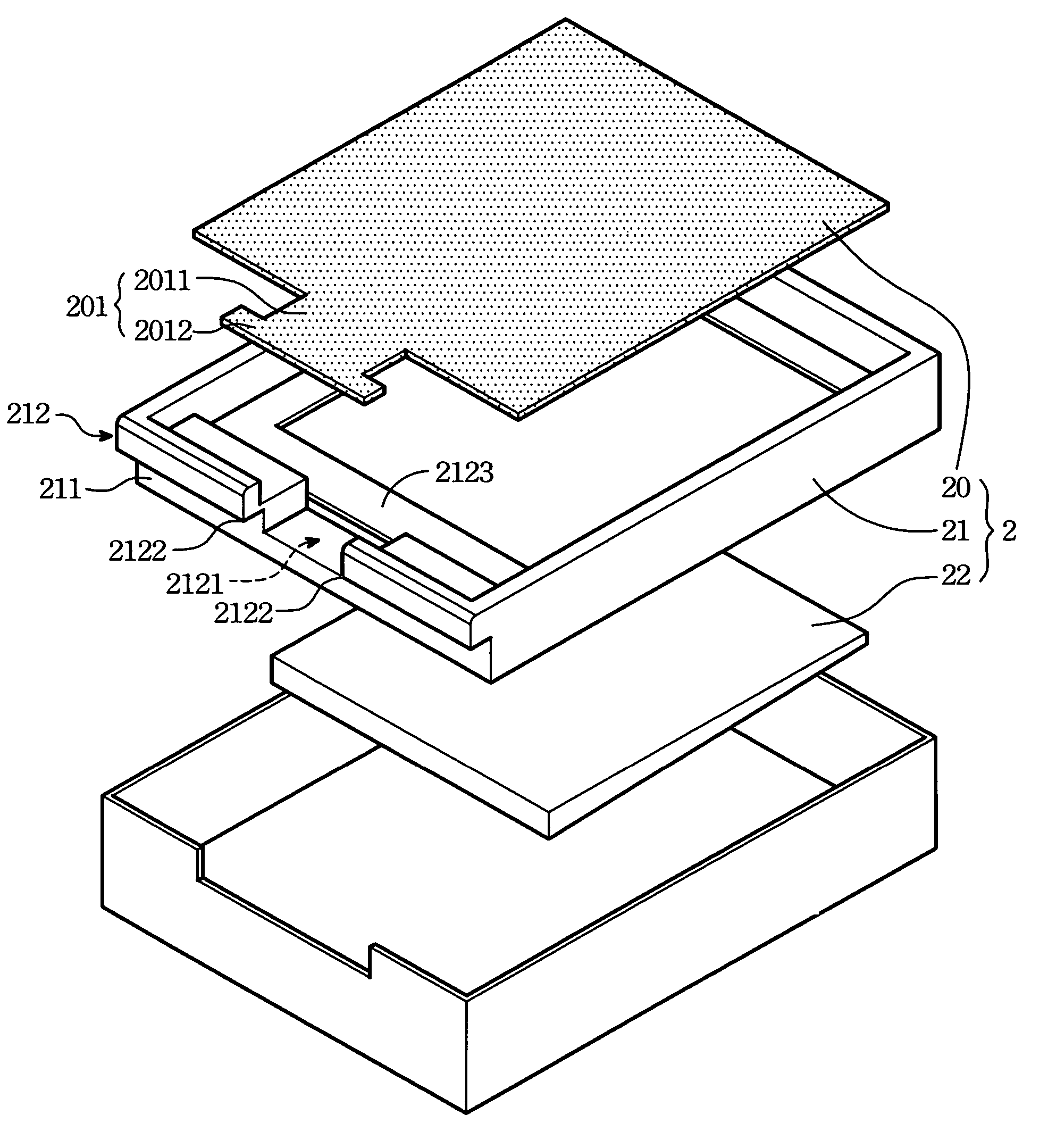
[0039]FIG. 7 illustrates a schematic view of the optical module of the present invention. The optical film 20 in FIG. 7 has a second lug 202 on aside opposite to the side with the first lug, and the positioning frame 21 includes a second opening 213 on its side wall 211, the position and the shape of the second opening 213 is corresponding to the second lug 202.

third embodiment

[0040]FIG. 8 illustrates a schematic view of the optical module of the present invention. The second lug 202 in FIG. 8 is formed on a side adjacent to the side with the first lug 201, and the positioning frame 21 includes a second opening 213 on the side wall 211, wherein the position and the shape of the second opening 213 is corresponding to the second lug 202.

[0041]To sum up, the present invention provides an optical film and a positioning frame that can be easily and conveniently assembled, and at the same time, restricts the movement of the optical film, effectively. The present invention can also reduce the manufacturing cost and prevent the light leakage from the lugs.

[0042]Another advantage of the present invention is that only a simple die block is required to manufacture the flange on the flange on the positioning frame, and therefore it's easy to apply into practice.


PUM

PropertyMeasurementUnit
widthaaaaaaaaaa
shapeaaaaaaaaaa
L shapeaaaaaaaaaa

Abstract

An optical module with an optical film and a positioning frame is disclosed. The positioning frame firmly fixes the optical film of the optical module so as to prevent the deviation of the optical film. The optical film has at least a first lug with a base portion and an expansion portion extending outwardly, wherein the width of the expansion portion is wider than the base portion. The positioning frame has a side wall and a flange. The flange is disposed on the side wall and has a first opening. The flange located at one side of the first opening has a first protrusion extending outwardly the side wall on the two sides of the first opening. The first opening is used to contain the base portion of the first lug, and the expansion portion of the first lug can be disposed under the first protrusion.

Description

BACKGROUND OF THE INVENTION[0001]1. Field of the Invention[0002]The invention relates to an optical module, and more particularly to an optical module with a positioning frame.[0003]2. Description of the Prior Art[0004]A liquid crystal display (LCD) is composed of two major parts, a backlight module and an LCD panel. The backlight module is utilized for providing uniform and steady illumination. The LCD panel is assembled on the illumination surface of the backlight module. By controlling the tilting angle of the LC (liquid crystal) molecules within the LCD panel, the optical transmission of the pixels within the LCD panel is adjusted to show the image.[0005]As mentioned above, the illumination of the LCD is provided by the backlight module. Therefore, brightness, uniformity, contrast, and viewing angle of a LCD are deeply influenced by the characteristics of the backlight module.[0006]In addition, various optical films, such as diffuser or prism sheet, are usually provided on the b...

Claims


Application Information

Patent Timeline
Patent Type & Authority Patents(United States)
IPC IPC(8): G02F1/1333G02F1/1335F21V7/04
CPCG02B6/0088G02F1/133606G02F1/133608
Inventor CHENG, CHI-CHENCHANG, CHE-CHIH
Owner AU OPTRONICS CORP
Why Eureka
Try Eureka