Fireplace insert

a technology for inserts and fireplaces, applied in the field of gas inserts, can solve the problems of fireplaces that are at risk of running afoul of building codes and gas appliance restrictions, and the top of the inserts have a very small clearance (sometimes as little as half an inch) between the bottom of the lintel and the top of the insert, so as to achieve effective heating and circulation of room air

Active Publication Date: 2012-05-01
MILES INDS
View PDF6 Cites 8 Cited by
  • Summary
  • Abstract
  • Description
  • Claims
  • Application Information

AI Technical Summary

Benefits of technology

[0014]According to one aspect of the invention, the insert assembly comprises an air guide plate extending forward of the top of the passageway outlet. In a more particular aspect, the guide plate is adjustably securable to extend at various distances and angles from the top of the passageway outlet, thereby allowing the pathway outlet to be above the top edge of the fireplace mouth. This in turn allows the top edge of the insert window to be less visible from outside the fireplace.

Problems solved by technology

As a result, there is usually very little clearance (sometimes as little as half an inch) between the top of the insert and the bottom of the lintel, baffle or smoke curtain that is provided in many wood burning fireplaces.
This tight fit presents challenges to installers who are required to fit ducting or liners from the flue onto the insert's vent connector.
Such modifications to the fireplace stand the risk of running afoul of building codes and gas appliance restrictions.
This may detract from the appearance of the fireplace by making the window look small in proportion to the overall fireplace.
This “porthole” effect is compounded by the fact that a portion of the front area of the insert is taken up by the outlet of the heat exchange passageway, leaving less space available for the window.

Method used


Image

  • Fireplace insert
  • Fireplace insert
  • Fireplace insert

Examples


Embodiment Construction

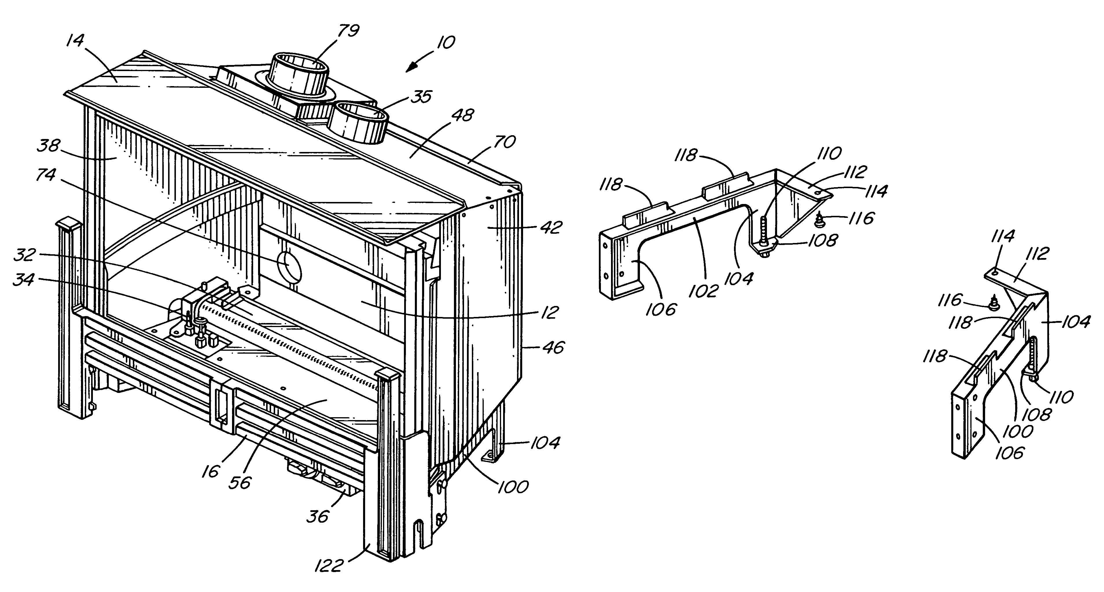
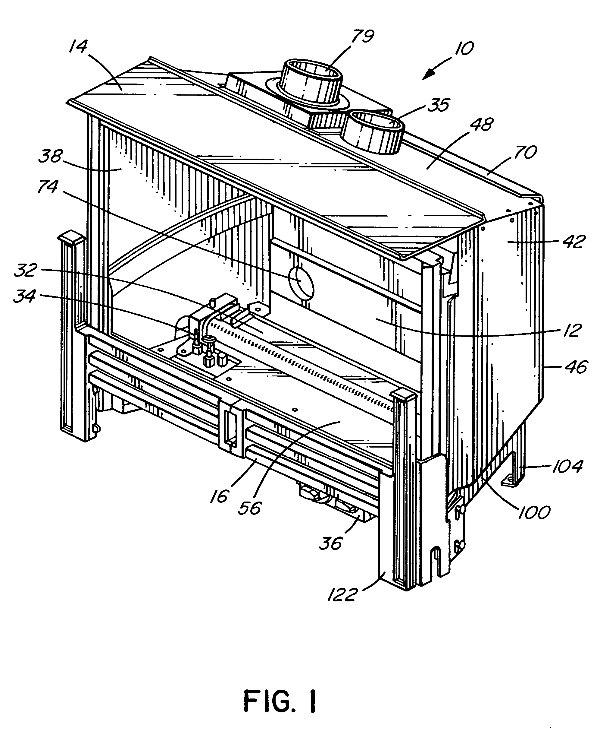
[0054]Referring to FIG. 1, the insert assembly 10 according to the preferred embodiment generally comprises an insert 12, a heated air exhaust guide plate 14 and a decorative fender 16.

[0055]Insert 12 includes a firebox, a burner assembly, a shroud partially surrounding the firebox and a heat exchange passageway, as described below. A log set 150 (seen only in FIG. 13), for example ceramic simulated logs, may be placed within insert 12 to enhance the resemblance of insert assembly 10 to an actual wood-burning fireplace.

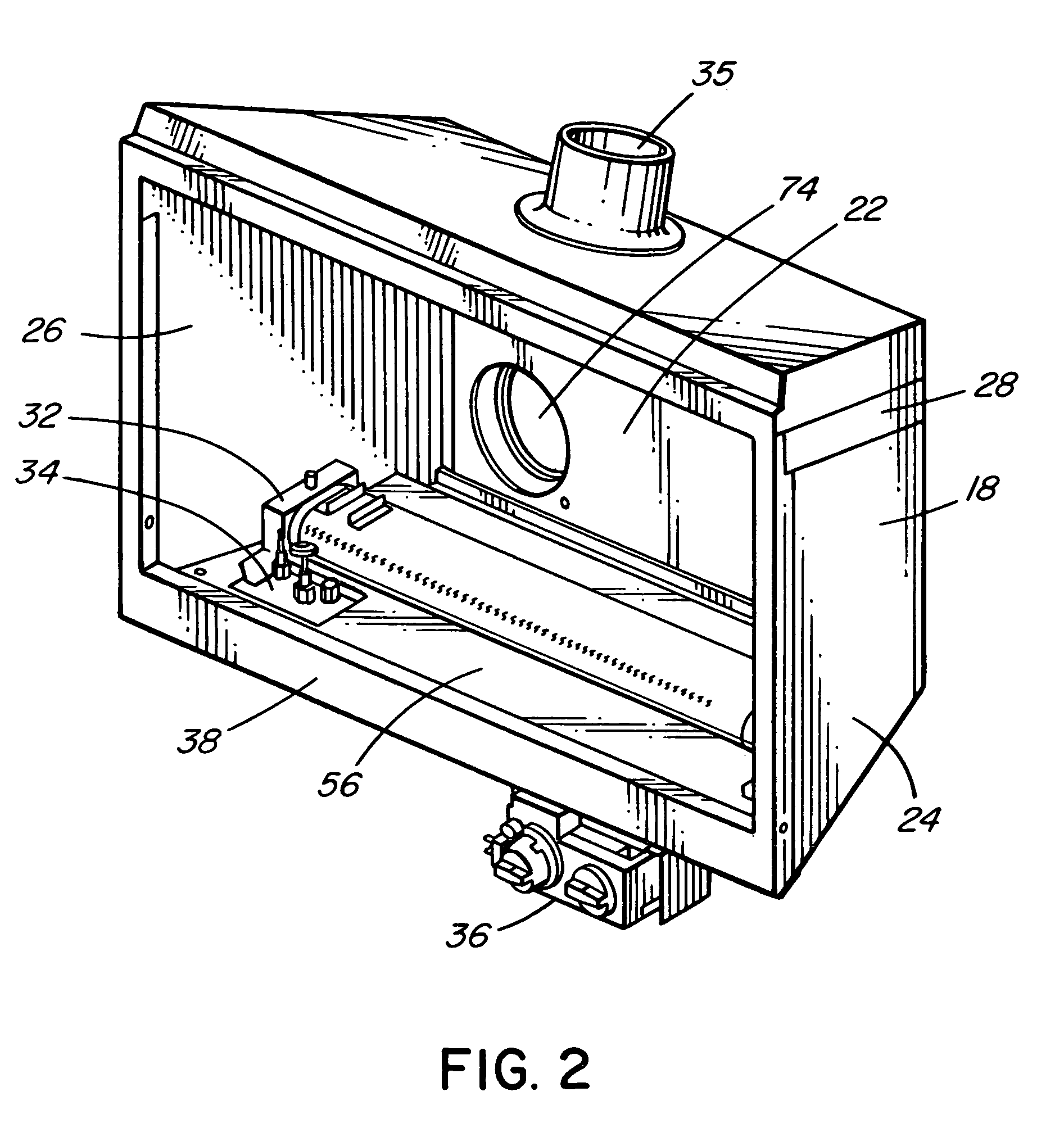
[0056]Referring to FIGS. 2 and 3, a front-opening firebox 18 is defined by a base 20 (which may be a full base or a base rim 20, as in the illustrated embodiment), a rear wall 22, at least one side wall (two opposed side walls 24, 26 are shown in the embodiment illustrated in FIGS. 2 and 3) and a firebox top 28. A baffle 30 controls the flow of combustion exhaust gases. Firebox cover 31 includes an aperture 33 to which is attached an exhaust collar 35.

[0057]A burner a...


PUM


Abstract

The invention provides an insert assembly to convert an existing fireplace hearth into a gas burning fireplace and a method for installing the insert assembly while conveying the appearance of a wood burning fireplace. The insert assembly comprises legs removably attachable to the base of the firebox for allowing the insert to be installed higher into the hearth. The inner walls of the firebox are colored so as to camouflage the structure of the assembly in the hearth and a decorative fender mimics a wood burning grill. Where the insert includes a heat exchanger, a guide plate is provided at the top of the insert to ensure that air exiting the heat exchange outlet at the top of the insert is directed into the room.

Description

FIELD OF THE INVENTION[0001]This invention relates to gas inserts designed to be retrofitted into fireplaces.BACKGROUND OF THE INVENTION[0002]It is known to provide gas fireplace inserts that are designed to be retrofitted into wood burning fireplaces. Examples of such inserts are disclosed in U.S. Pat. No. 5,191,877 to Shimek, U.S. Pat. No. 5,752,500 to Jamieson et al., U.S. Pat. No. 6,029,655 to Hussong et al. and U.S. Pat. No. 6,116,232 to Valters et al.[0003]The use and installation of gas fireplace inserts are constrained by certain conditions. Inserts of the sealed combustion type are often provided with an integral heat exchange passageway around the firebox into which room air is drawn in, heated and expelled back into the room. The pathway is defined by an outer wall of the insert that is spaced from the top and back walls of the firebox. Circulation of air through the pathway is often ensured by a blower mounted beneath or to the rear of the firebox. Legs or brackets suppo...

Claims


Application Information

Patent Timeline
Patent Type & Authority Patents(United States)
IPC IPC(8): F24B1/188
CPCF24B1/1808F24C3/002
Inventor MILES, MARTINMILES, GARRYBOOK, BYRONSTEVENS, JOHN
Owner MILES INDS
Why Eureka
Try Eureka