

Micro-evaporator
a micro-evaporator and evaporator technology, applied in the field of micro-evaporators, can solve the problems of evaporators that are not compact, low power density, and can cause vapor bursts or vapor bubbles, etc., and achieve the effect of simplifying production, contributing to compact design, and simplifying production of micro-evaporators
- Summary
- Abstract
- Description
- Claims
- Application Information
AI Technical Summary
Benefits of technology
Problems solved by technology
Method used
Image

Examples
Embodiment Construction
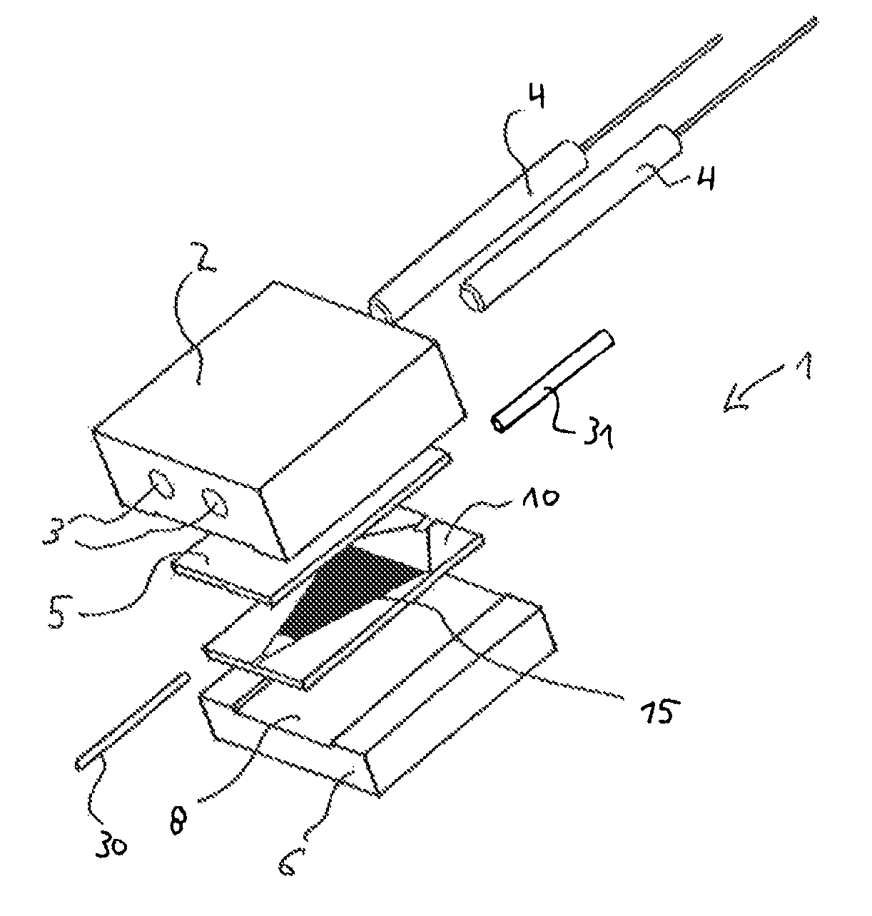
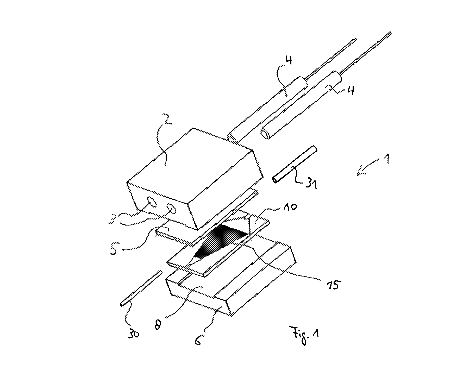
[0043]FIG. 1 shows a micro-evaporator 1 having (from top to bottom) a heating plate 2 with holes 3 to receive heating elements 4, a cover plate 5, a micro-evaporator plate 10 and a baseplate 6. The cover plate 5 lies on the micro-evaporator plate 10 that has the micro-structured micro-evaporator channels in a trapezoidal area 15 as explained in detail with reference to the subsequent Figures.
[0044]The micro-evaporator plate 10 where the liquid is evaporated is connected to a feed line 30 for the liquid to be evaporated and a discharge line 31 to remove the vapor. The micro-evaporator plate 10 is in a groove-like recess 8 of the base plate 6. Overall, this yields a cuboid micro-evaporator with outer dimensions less than 50 mm that is expandable with additional micro-evaporator plates 10 and inserted intermediate plates 7 as explained with reference to FIGS. 9a and 9b.
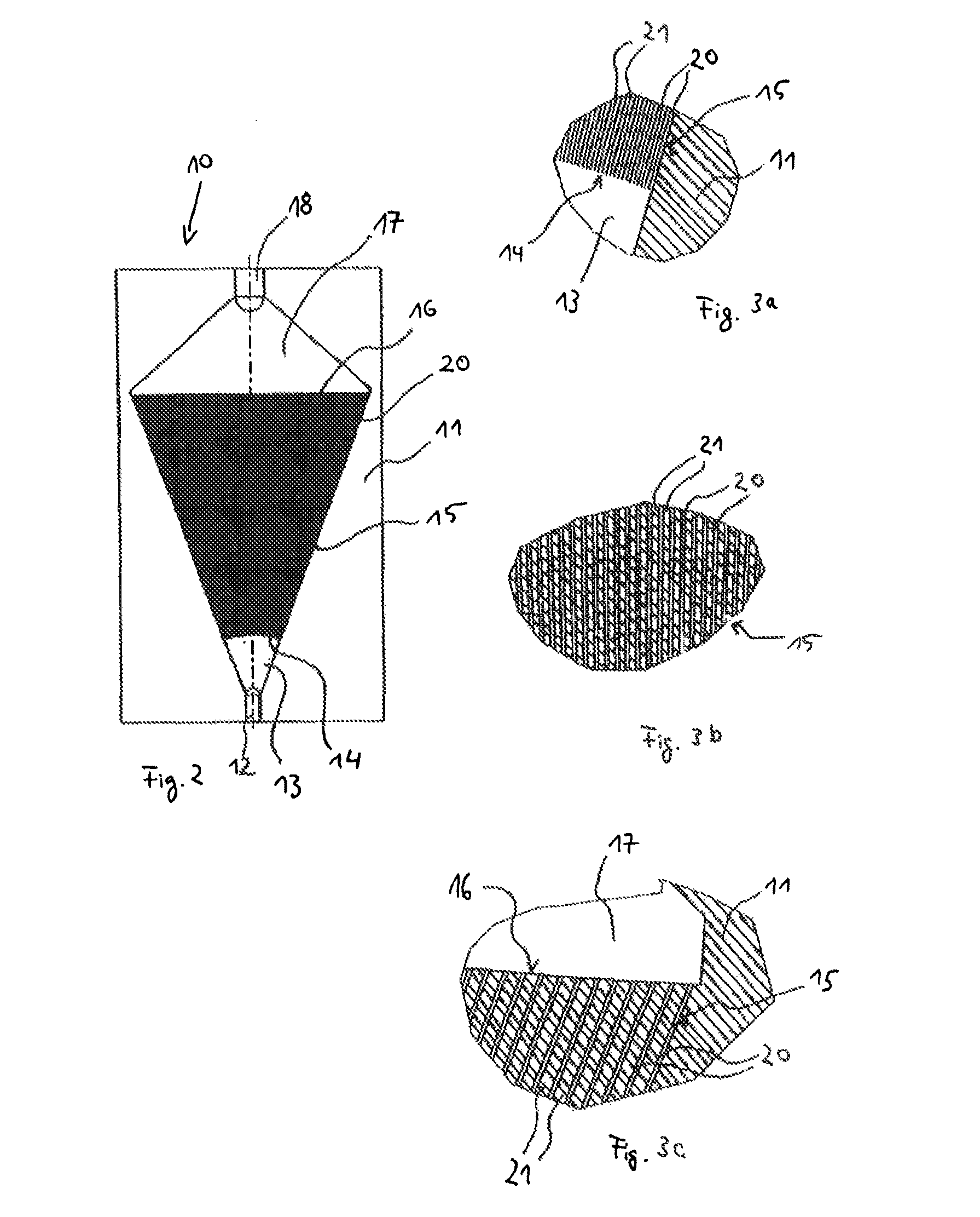
[0045]FIG. 2 shows a plan view of the front side 11 of the micro-evaporator plate 10 shown in FIG. 1, said plate cons...
PUM
 Abstract
Description
Claims
Application Information