
Method and apparatus for a spindle with servo feed control

a technology of servo feed control and method and apparatus, which is applied in the field of manufacturing, can solve the problems of difficult configuration and increase the quality of the hol

Active Publication Date: 2012-05-01
THE BOEING CO
View PDF18 Cites 44 Cited by
  • Summary
  • Abstract
  • Description
  • Claims
  • Application Information

AI Technical Summary

Benefits of technology

Enables flexible configuration for various drilling operations like positive feed, peck and feed, and countersinking with programmable feed rates and retract distances, improving hole quality and reducing cycle time by eliminating the need for mechanical adjustments and air valve control.

Problems solved by technology

Further, this type of drilling also may reduce the amount of heat applied to the object, which also may increase the quality of the hole.
Currently, these drills are difficult to configure for changes between feed forward drilling, peck and feed drilling, and with countersink drilling processes.

Method used


Image

  • Method and apparatus for a spindle with servo feed control
  • Method and apparatus for a spindle with servo feed control
  • Method and apparatus for a spindle with servo feed control

Examples


Embodiment Construction

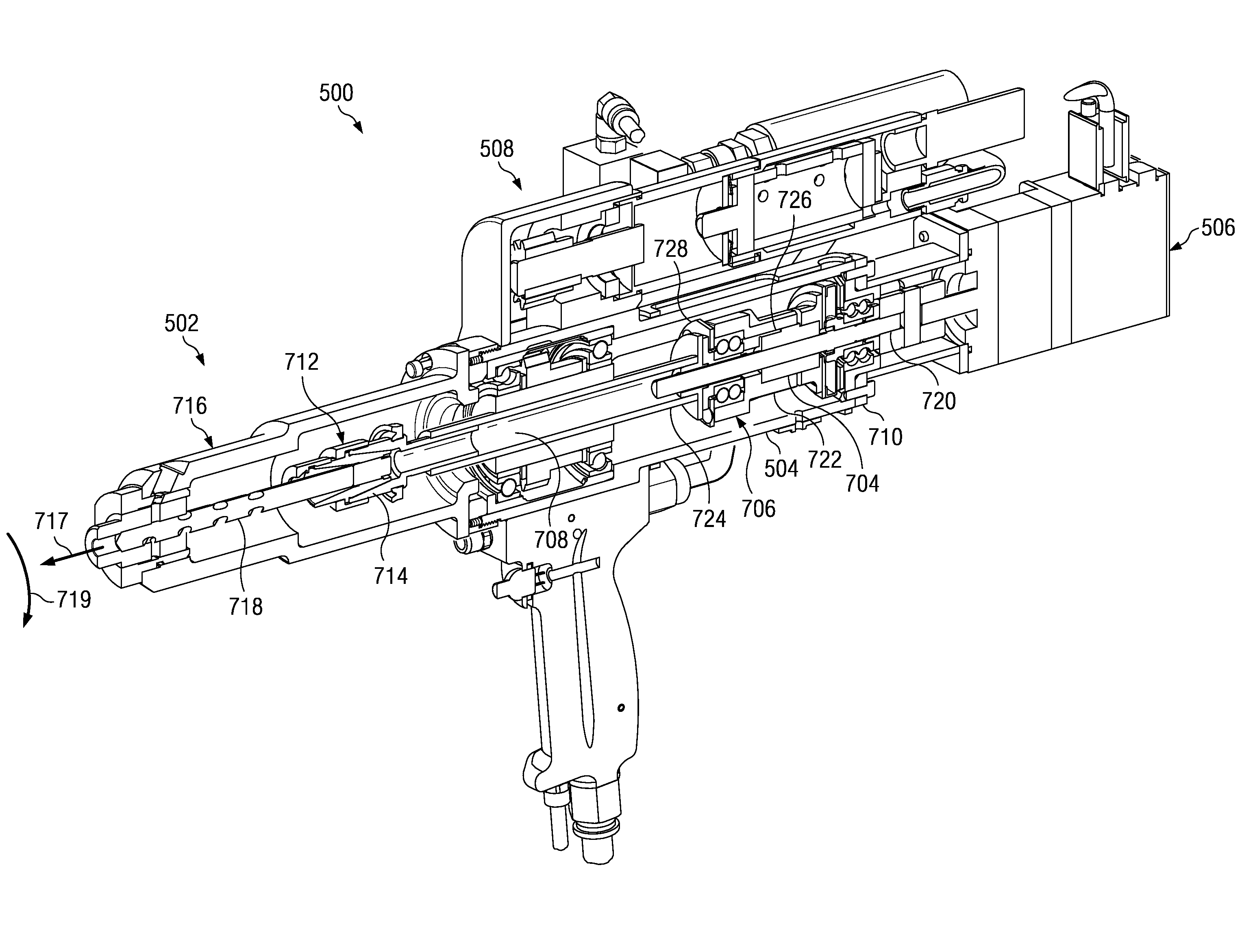
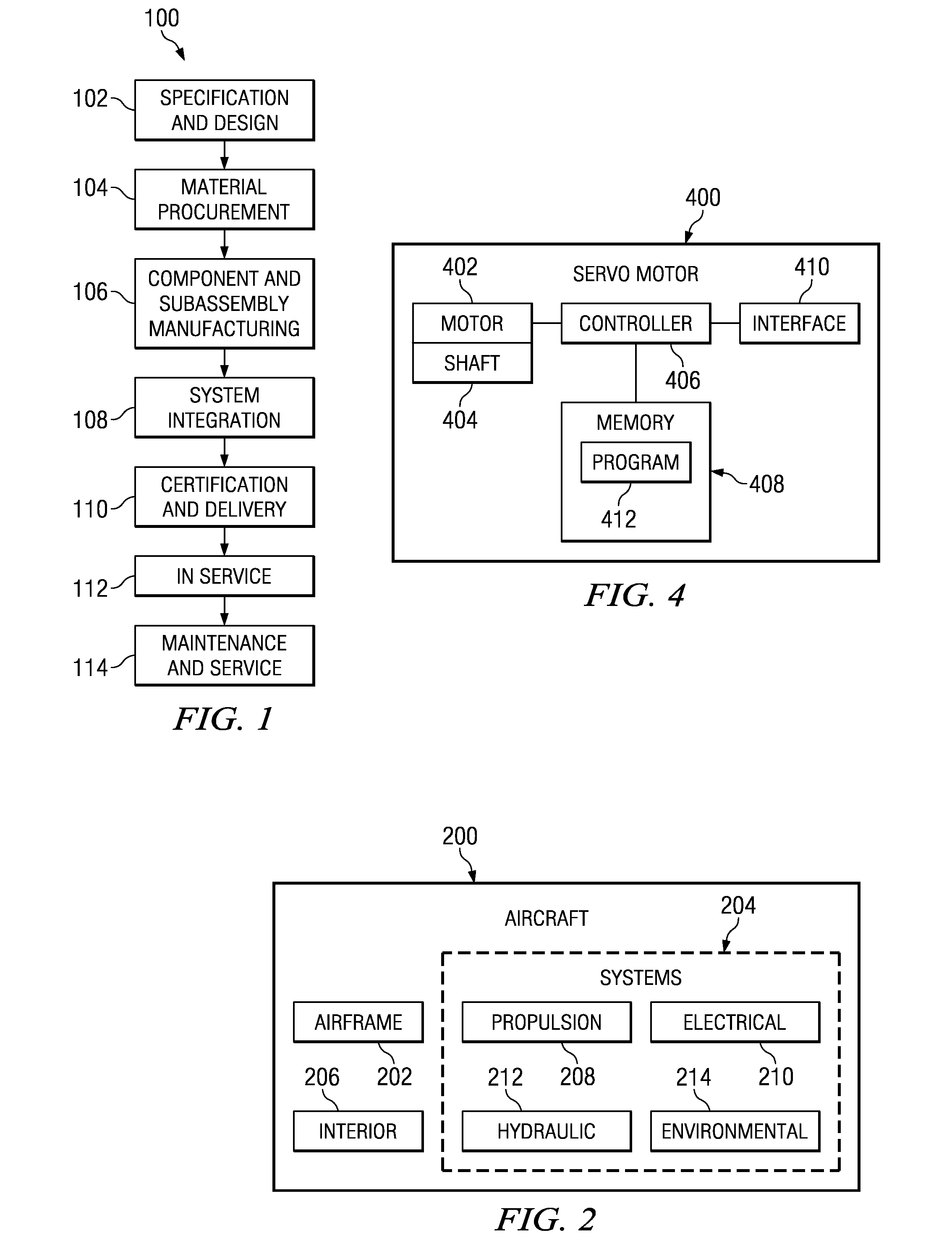
[0033]Referring more particularly to the drawings, embodiments of the disclosure may be described in the context of the aircraft manufacturing and service method 100 as shown in FIG. 1 and aircraft 200 as shown in FIG. 2. Turning first to FIG. 1, a diagram illustrating an aircraft manufacturing and service method is depicted in accordance with an advantageous embodiment. During pre-production, exemplary aircraft manufacturing and service method 100 may include specification and design 102 of aircraft 200 in FIG. 2 and material procurement 104. During production, component and subassembly manufacturing 106 and system integration 108 of aircraft 200 in FIG. 2 takes place. Thereafter, aircraft 200 in FIG. 2 may go through certification and delivery 110 in order to be placed in service 112. While in service by a customer, aircraft 200 in FIG. 2 is scheduled for routine maintenance and service 114, which may include modification, reconfiguration, refurbishment, and other maintenance or s...


PUM

PropertyMeasurementUnit
movementaaaaaaaaaa
movementaaaaaaaaaa
axial speedsaaaaaaaaaa

Abstract

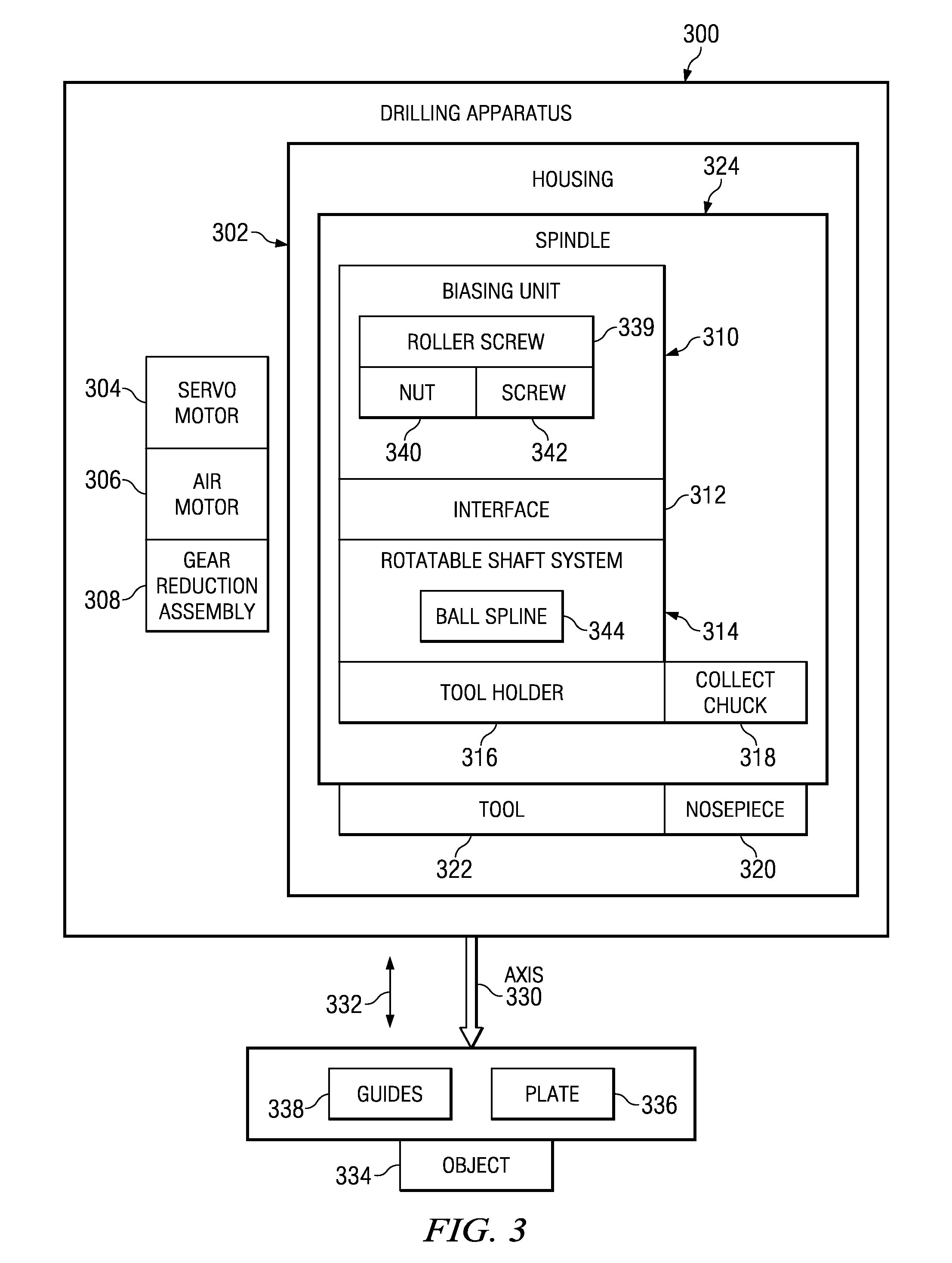
A method and apparatus for a power feed drill. The power feed drill comprises a servo motor, a roller screw, a ball spline shaft, an air motor, and a collet chuck. The roller screw is rotatably mounted to the servo motor. The ball spline shaft has a first end connected to the roller screw, wherein rotation of the roller screw in a first direction moves the ball spline shaft in the first direction and wherein rotation of the roller screw in a second direction moves the ball spline shaft in an opposite direction to the first direction along an axis. The air motor is capable of transmitting rotation motion to the ball spline shaft to rotate around the axis. The collet chuck is fixably attached to a second end of the ball spline shaft, wherein the collet chuck is adapted to receive a tool.

Description

BACKGROUND INFORMATION[0001]1. Field[0002]The present disclosure relates generally to manufacturing and in particular to a method and apparatus for drilling holes in objects. Still more particularly, the present disclosure relates to a method and apparatus for drilling and countersinking with a component that may be moved forward and backwards in an axial direction.[0003]2. Background[0004]Manufacturing involves the use of tools and / or labor to create items for use or sale. In aerospace manufacturing, these items may include, for example, aircraft, aircraft parts, missiles, rockets, and / or spacecraft. In manufacturing various items, a number of different operations may be performed. For example, these operations may include, for example, extrusion, pressing, rolling, piercing, machining, drilling, routing, and curing.[0005]With respect to drilling, a drill is used to create holes or channels that are typically cylindrical in solid materials. A drill is a tool with a rotating section...

Claims


Application Information

Patent Timeline
Patent Type & Authority Patents(United States)
IPC IPC(8): B23B47/18B23B35/00
CPCB23Q5/225B23Q5/326Y10S408/702Y10T408/73Y10T408/03Y10T408/68Y10T408/23
Inventor MATHIS, DENNISMATLACK, MIKEMARTIN, SCOTT ANTHONYFRITSCHE, DAVID L.
Owner THE BOEING CO
Learn More