

Pulse doppler radar device
a radar device and doppler technology, applied in the direction of measurement devices, instruments, using reradiation, etc., can solve the problems of difficult installation of radar devices and high system cos
- Summary
- Abstract
- Description
- Claims
- Application Information
AI Technical Summary
Benefits of technology
Problems solved by technology
Method used
Image

Examples
first embodiment
The First Embodiment
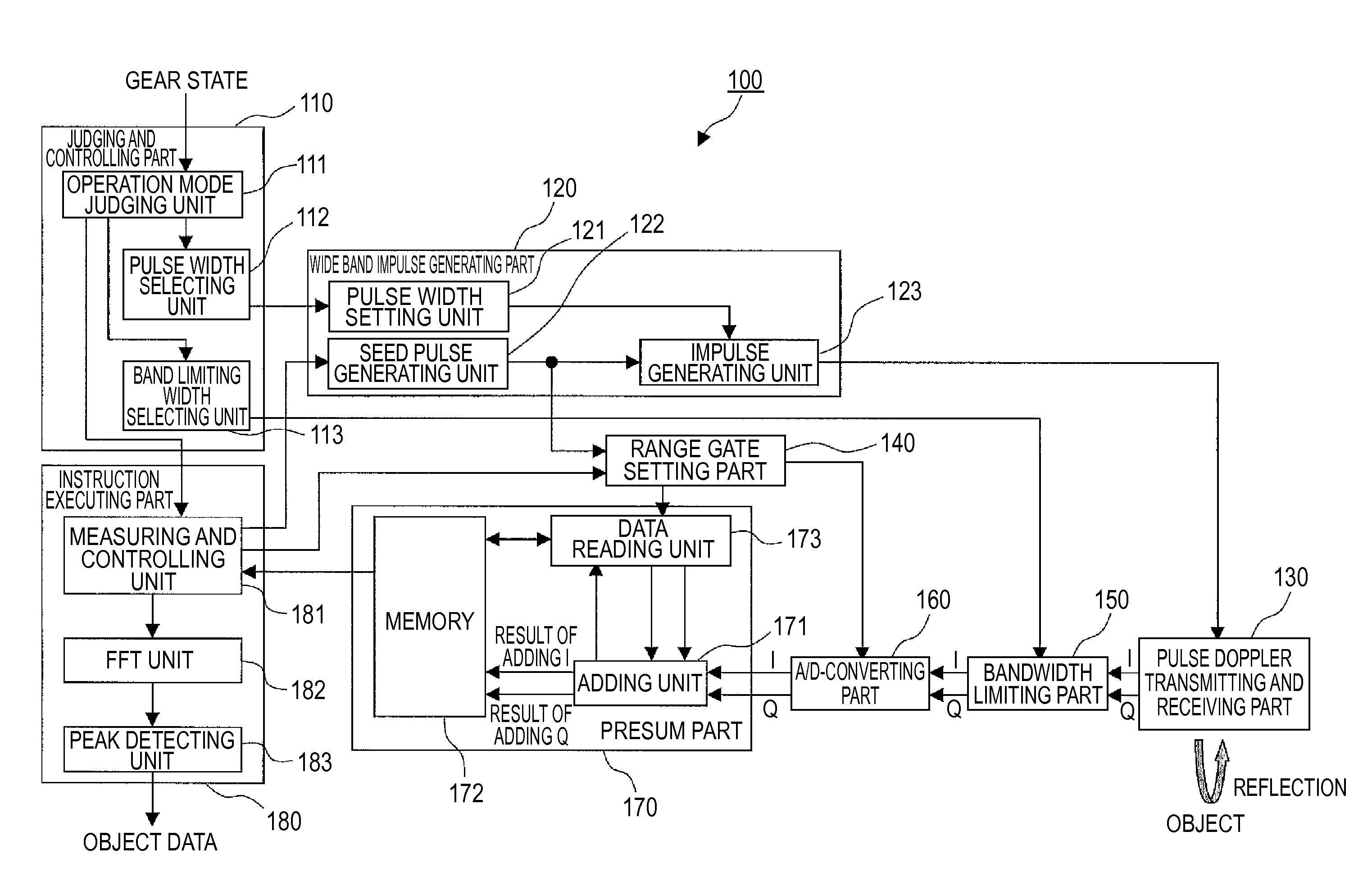
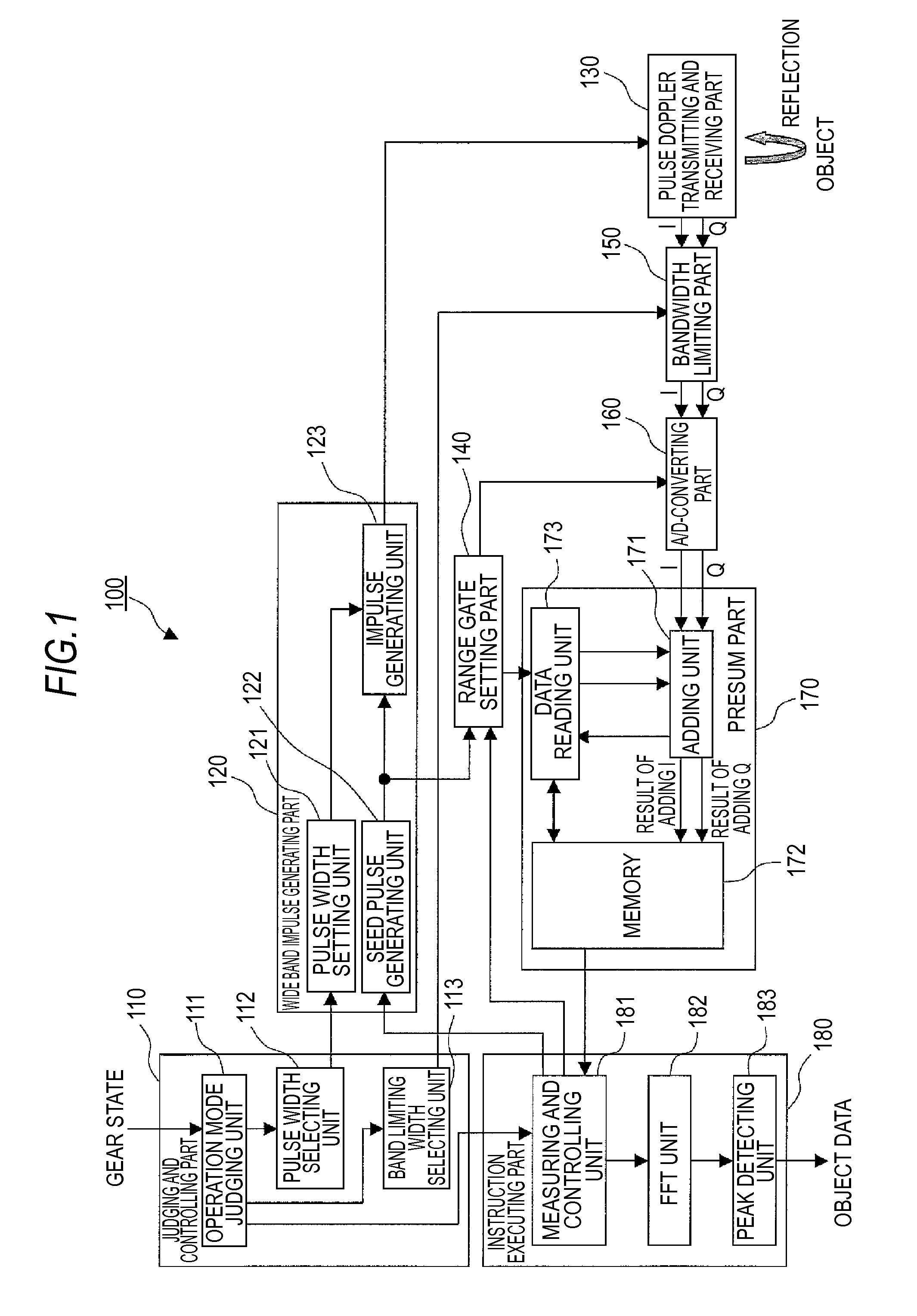
[0025]A preferred embodiment of a pulse Doppler radar device according to the present invention will be described in detail below, with reference to the drawings. Here, each of component parts having a similar function is designated by the similar symbol for simplifying a drawing and a description. In the following, the description is given to a case where the pulse Doppler radar device according to the present invention is used with being mounted in a vehicle, for example.
[0026]The pulse Doppler radar device according to the first embodiment of the present invention realizes an operation mode of such as a collision detecting or the like, in which objects having a large relative velocity are detected with a relatively low range resolution, and another operation mode of such as a parking support or the like, in which objects having a small relative velocity are detected with a relatively high range resolution. First, an operating condition required for each of the...
second embodiment
The Second Embodiment
[0090]A pulse Doppler radar device according to the second embodiment of the present invention is configured to use a velocity of a vehicle for judging an operation mode of the radar. The operation mode judging unit 111 receives a velocity of the vehicle, instead of the signal of the gear state used in the first embodiment, from a predetermined controlling device in the vehicle. Using the velocity of the vehicle as a judgment reference data, whether the pulse Doppler radar device 100 should be used in the parking support mode or in the collision detecting mode is judged.
[0091]As one example, the pulse Doppler radar device 100 operates in the parking support mode when the operation mode judging unit 111 judges that the velocity of the vehicle is low (not higher than 20 km / h). On the other hand, the pulse Doppler radar device 100 operates in the collision detecting mode when the operation mode judging unit 111 judges that the velocity of the vehicle is high (highe...
third embodiment
The Third Embodiment
[0094]A pulse Doppler radar device according to the third embodiment of the present invention is configured to switch the operation mode depending on whether or not a large size object exists within a detecting range of the radar. That is to say, the pulse Doppler radar device normally scans fast within a wide range using a pulse signal having a narrow bandwidth (0.5 GHz for example), having a relatively low range resolution. When a large size object is detected within the detecting range of the radar, the pulse Doppler radar device starts scanning with a higher range resolution within a range before the large size object, using a pulse signal having a wider bandwidth (2 GHz for example). For the purpose of judging an existence of a large size object, for example, the instruction executing part 180 may be configured to calculate a radar cross section, using the integrated I and Q signals which are input from the presum part 170.
[0095]When a large size object (cor...
PUM
 Abstract
Description
Claims
Application Information