Inertia sensor and inertia detector device

a detector device and sensor technology, applied in the direction of turning-sensitive devices, acceleration measurement using interia forces, instruments, etc., can solve the problems of inability to obtain a sufficient s/n ratio, limited usable application, and difficulty in applying the technology of patent document 4 to the structural body

Active Publication Date: 2012-05-08
SONY CORP
View PDF9 Cites 49 Cited by
  • Summary
  • Abstract
  • Description
  • Claims
  • Application Information

AI Technical Summary

Problems solved by technology

However, since these inertia sensors separate the displacement of the acceleration and the angular velocity obtained from one movable body by means of signal processing, it is not possible to obtain a sufficient S / N ratio (Signal to Noise Ratio) with respect to a cross-axis sensitivity and a disturbance noise, and an usable application is limited.
Thus, it is difficult to apply the technology of Patent Document 4 to the structural body as disclosed in Patent Document 3.

Method used


Image

  • Inertia sensor and inertia detector device
  • Inertia sensor and inertia detector device
  • Inertia sensor and inertia detector device

Examples


Embodiment Construction

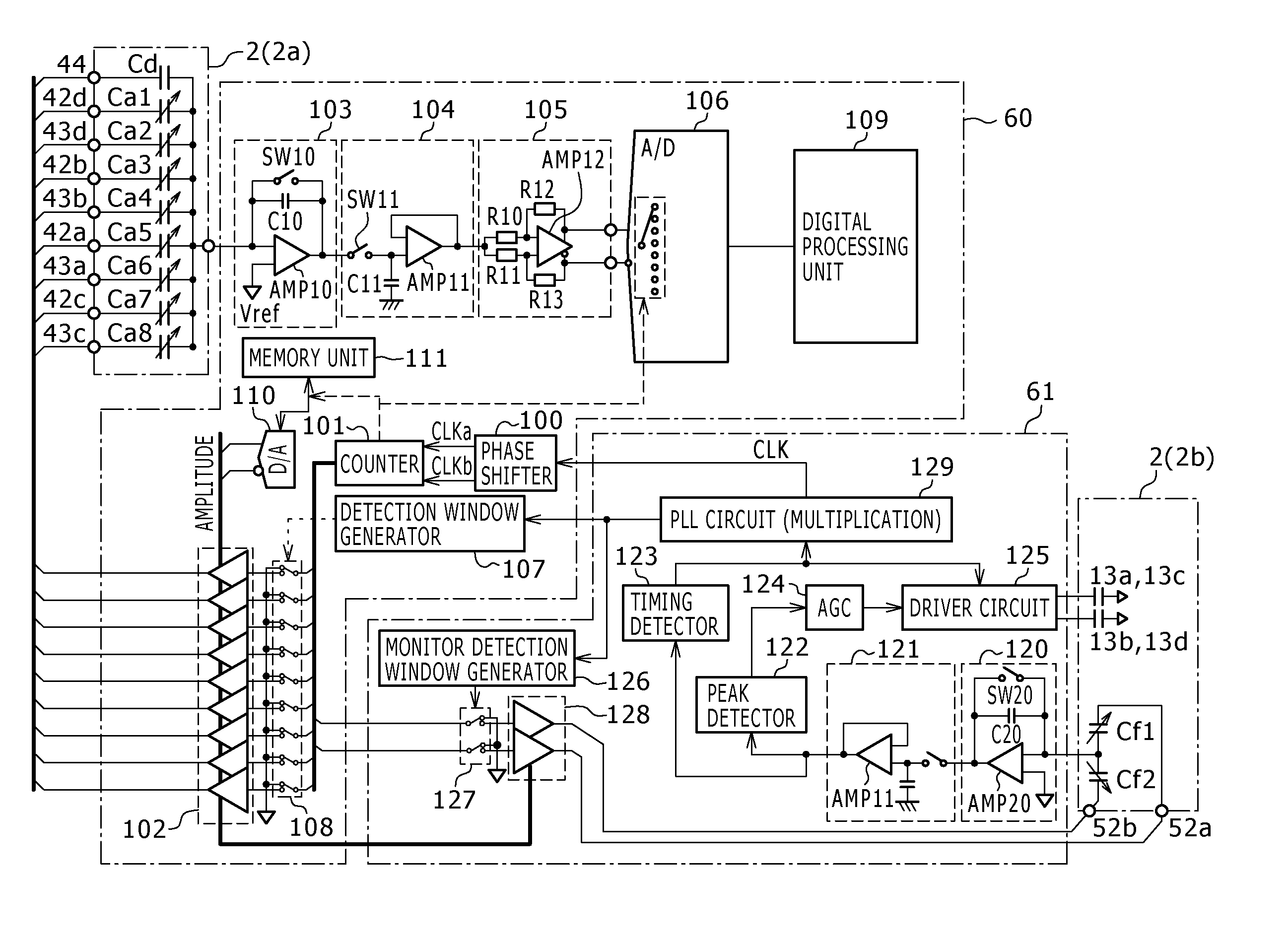
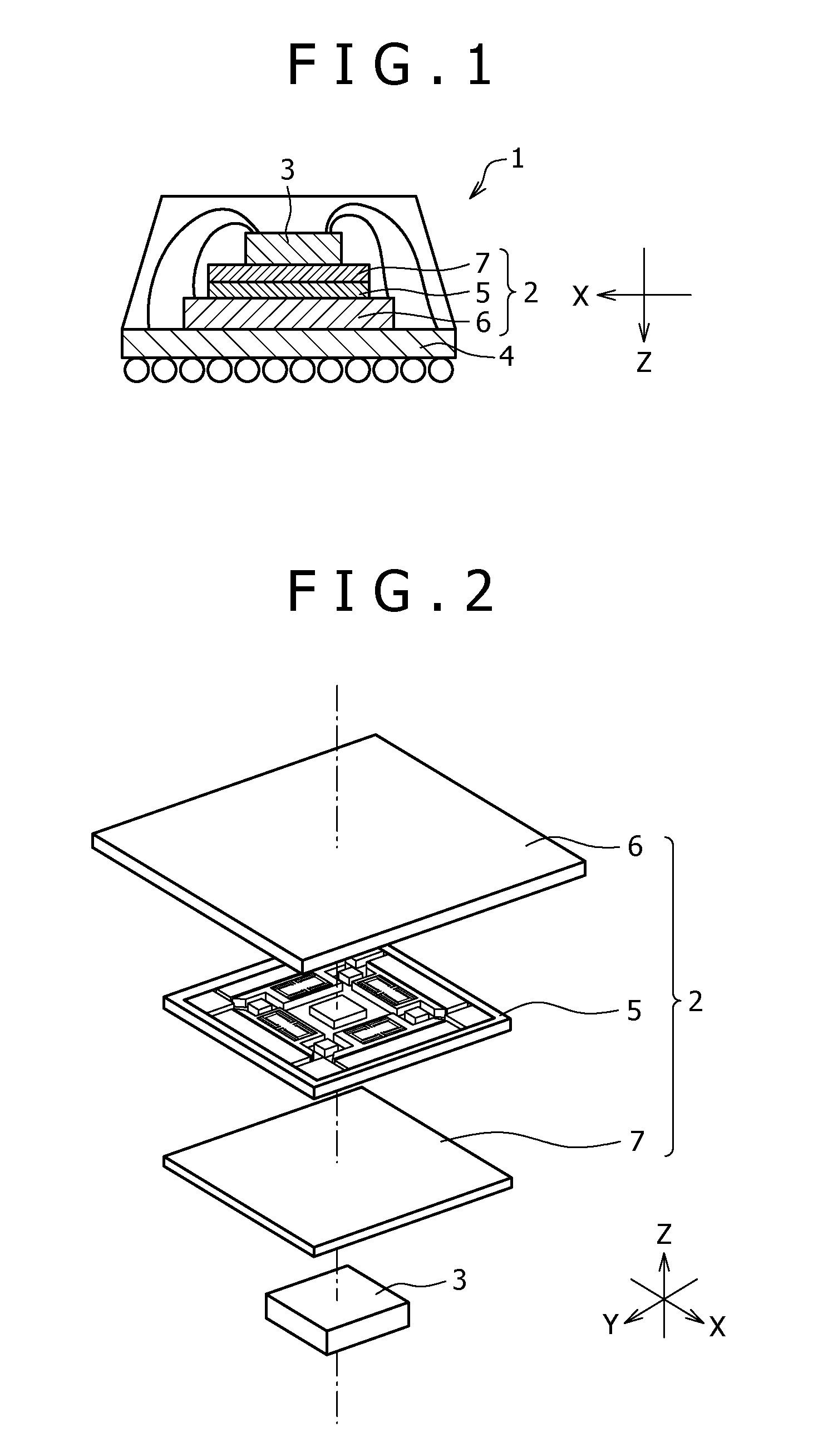
[0044]An inertia sensor in the embodiment has a structural body provided with a plurality of variable blocks where a variable capacitance element is formed whose capacitance value changes in accordance with applied inertial force and a fixed block where a fixed capacitance element is formed whose capacitance value is fixed, in which each variable block can be reciprocally vibrated in a predetermined direction, and a detector circuit (equivalent to an example of detector device) for detecting a value of the applied inertial force based on the capacitance values of the variable capacitance element and the fixed capacitance element in which each variable is reciprocally vibrated, thus allowing detection of the angular velocity at three axes and the acceleration at three axes.

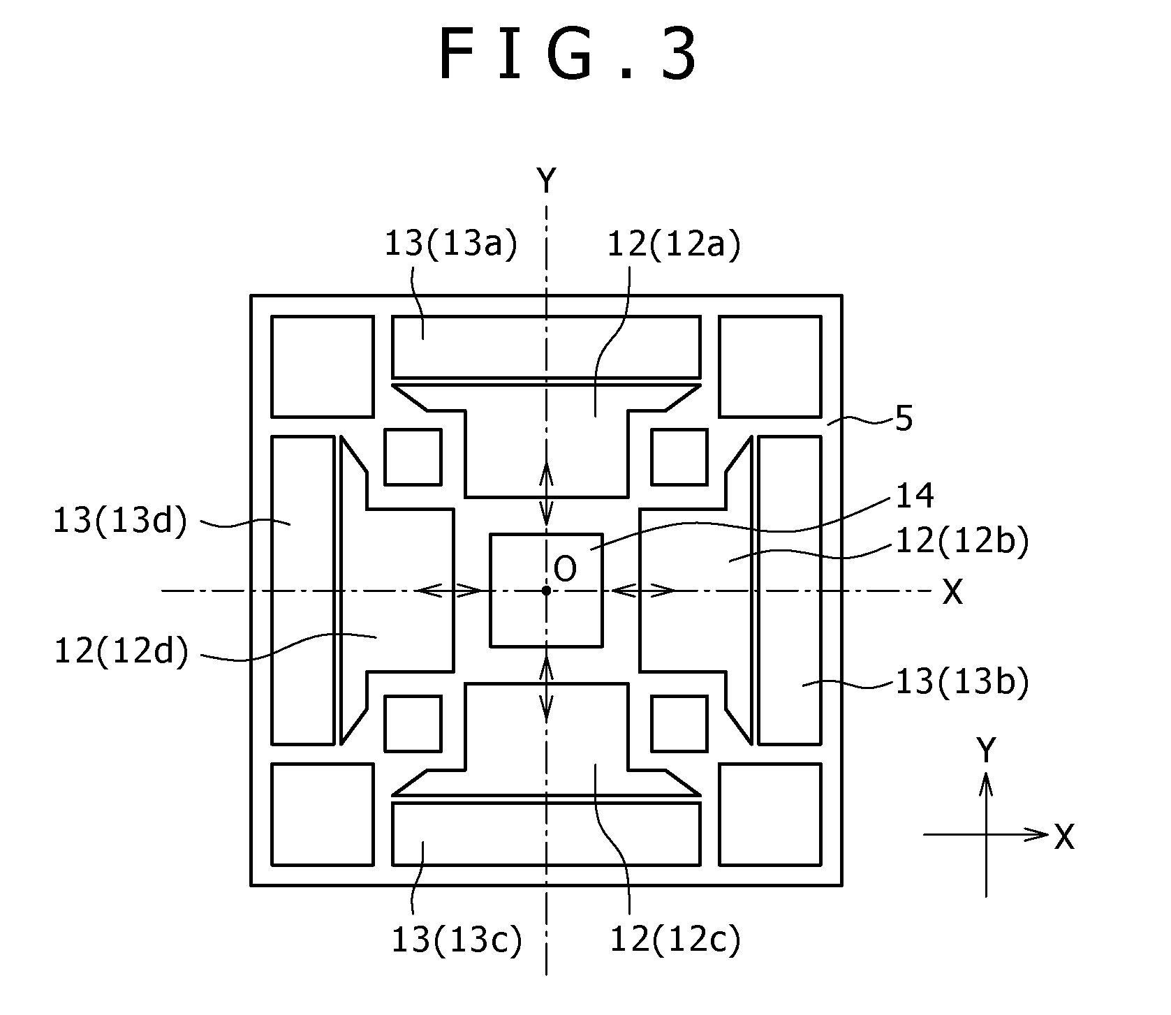
[0045]The structural body has a plurality of variable blocks, in which one pair of the variable blocks are arranged in a position where laterally symmetrical and another pair of the variable blocks are arranged in ...


PUM


Abstract

A detector device includes a drive circuit for outputting a drive pulse signal for displacing the variable block, a detection pulse signal applying unit by which the variable capacitance elements and the fixed capacitance element whose one end is connected in common are respectively applied, at their other ends, with detection pulse signals with a plurality of phases each having a predetermined phase difference at a timing synchronized with the drive pulse signal, and an inertia detection unit for detecting a difference in capacitance value between the variable capacitance elements to which the detection pulse signal having the phase difference is applied, or between the fixed capacitance element and the variable capacitance element, and detecting the applied inertial force based on the difference.

Description

CROSS-REFERENCES TO RELATED APPLICATIONS[0001]The present document contains subject matter related to Japanese Patent Application No. 2007-302297 filed in the Japanese Patent Office on Nov. 21, 2007, the entire content of which being incorporated herein by reference.BACKGROUND OF THE INVENTION[0002]1. Field of the Invention[0003]The present invention relates to an inertia sensor for detecting an angular velocity and acceleration, and a detector device thereof.[0004]2. Description of the Related Art[0005]An inertia sensor has been known that is attached to an object and can detect acceleration and an angular velocity which are produced when the object carries out acceleration movement and angular velocity movement.[0006]This inertia sensor detects individual acceleration per each axial direction at X-axis, Y-axis, or Z-axis defined as the 3-dimensional space, and detects individually the angular velocity per each axis which serves as rotation axis, whereby the acceleration and the an...

Claims


Application Information

Patent Timeline
Patent Type & Authority Patents(United States)
IPC IPC(8): G01C19/56G01C19/5726G01C19/574G01P15/125G01P15/18H01L29/84
CPCG01C19/56G01P15/125G01P15/14G01P15/18G01C19/5776H01L2224/48091H01L2224/48227H01L2924/15311H01L2924/181H01L2924/00012H01L2924/00014
Inventor SAMESHIMA, TOSHIHISA
Owner SONY CORP
Why Eureka
Try Eureka