
Intermediate lock pin type variable valve timing unit for vehicle and continuously variable valve timing device using the same

a technology of variable valve timing and lock pin, which is applied in the direction of valve arrangement, yielding coupling, coupling, etc., can solve the problem that the lock pin b>131/b> cannot be properly locked into the pin locking part, and achieve the effect of shortening the development tim

Active Publication Date: 2012-05-08
HYUNDAI MOTOR CO LTD +1
View PDF21 Cites 6 Cited by
  • Summary
  • Abstract
  • Description
  • Claims
  • Application Information

AI Technical Summary

Benefits of technology

[0017]Various aspects of the present invention are directed to provide an intermediate lock pin (ILP) type continuously variable valve timing device for a vehicle, which can shorten development time through mounting of an ILP type oil control valve within the range where the layout of an engine room is not changed and to provide an intermediate lock pin (ILP) type continuously variable valve timing device for a vehicle, which can make a rotor completely locked into a stator when an engine stops, and thus prevent the rotor from bumping against the stator and being damaged with noise occurrence when the rotor is re-started.
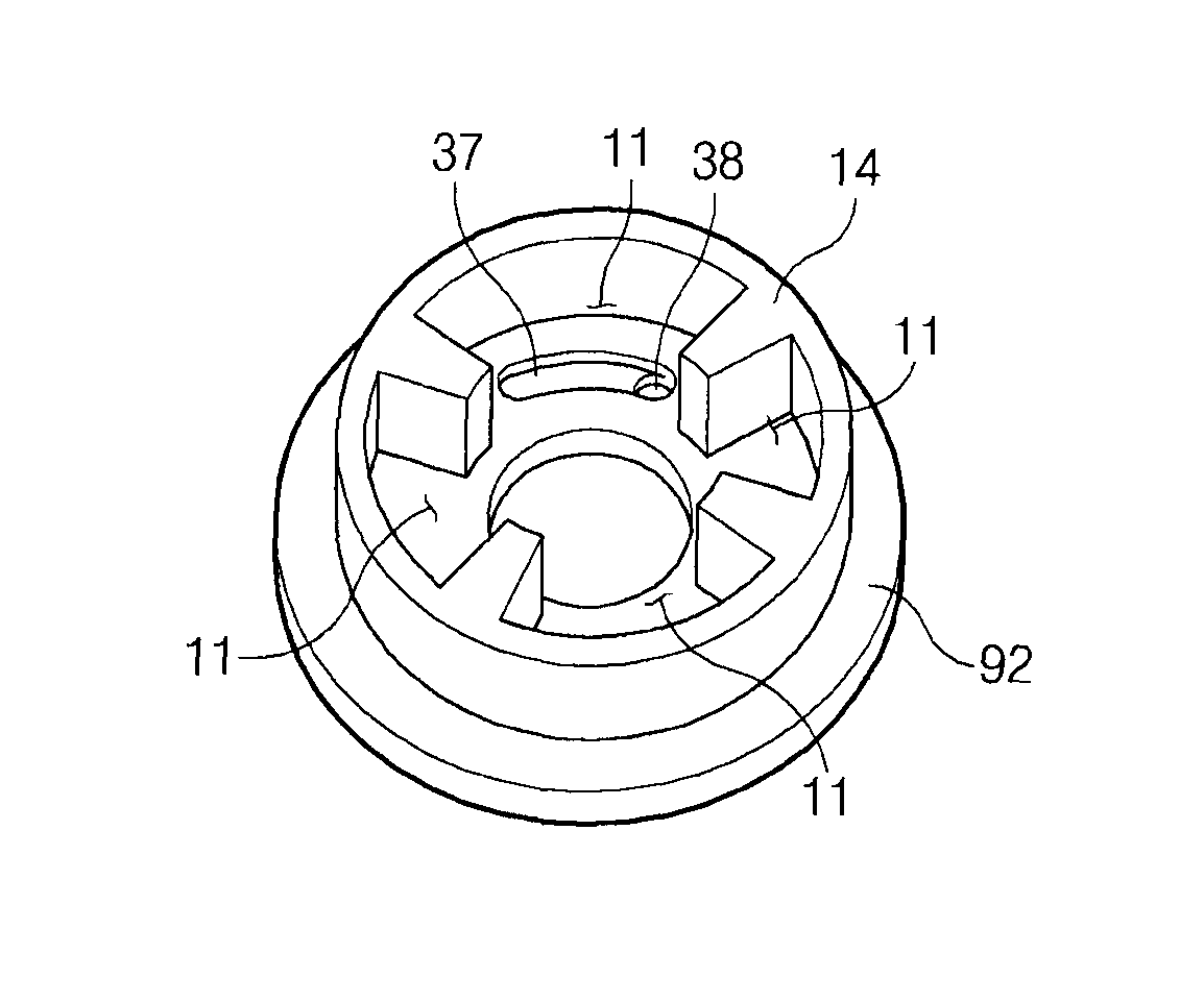
[0019]The lock maintaining portion may include a guide projection formed to the rotor and elastically projectable from the rotor; a guide groove formed on the stator to receive the guide projection there in and guide the guide projection; and a locking groove formed at a portion of the guide groove to selectively lock the guide projection therein when the engine stops working, wherein a circumferential thickness between the locking projection and a distal end portion of the vane is shorter than a circumferential distance between the locking groove and the partition wall of the stator to prevent the vane from bumping against the partition wall of the stator.
[0023]In another aspect of the present invention, the lock maintaining portion may include a guide projection formed to extend from the rotor, and provided with a locking hole formed on one side thereof; a guide groove formed on the stator to receive the guide projection therein and guide the guide projection; and a locking projection formed at an end portion of the guide groove to be selectively locked into the locking hole when the engine stops working, wherein a circumferential thickness between the locking projection and a distal end portion of the vane is shorter than a circumferential distance between the locking groove and the partition wall of the stator to prevent the vane from bumping against the partition wall of the stator.

Problems solved by technology

Also, in the conventional ILP type variable valve timing device, the lock pin 131 may not be properly locked into the pin locking part when the engine stops working.

Method used


Image

  • Intermediate lock pin type variable valve timing unit for vehicle and continuously variable valve timing device using the same
  • Intermediate lock pin type variable valve timing unit for vehicle and continuously variable valve timing device using the same
  • Intermediate lock pin type variable valve timing unit for vehicle and continuously variable valve timing device using the same

Examples


Embodiment Construction

[0041]Reference will now be made in detail to various embodiments of the present invention(s), examples of which are illustrated in the accompanying drawings and described below. While the invention(s) will be described in conjunction with exemplary embodiments, it will be understood that present description is not intended to limit the invention(s) to those exemplary embodiments. On the contrary, the invention(s) is / are intended to cover not only the exemplary embodiments, but also various alternatives, modifications, equivalents and other embodiments, which may be included within the spirit and scope of the invention as defined by the appended claims.

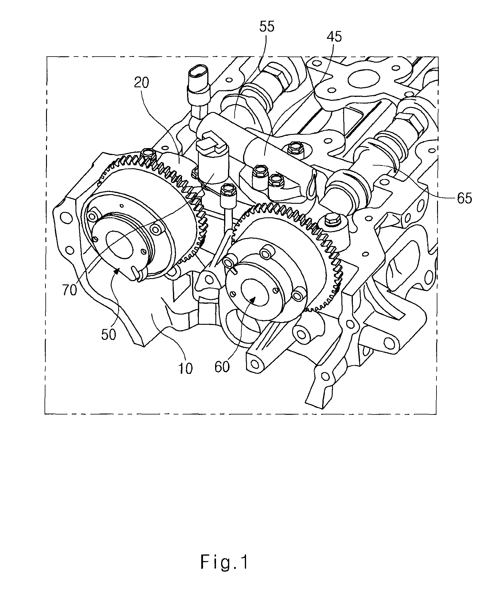
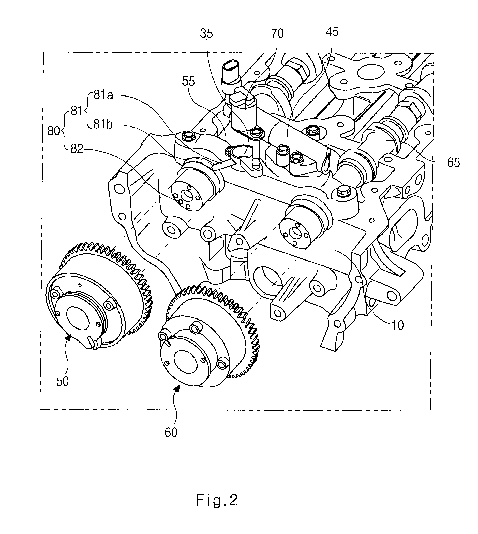
[0042]In various embodiments of the present invention, FIGS. 1 and 2 illustrate an ILP type continuously variable valve timing device for a vehicle according to various embodiments of the present invention.

[0043]The continuously variable valve timing device according to various embodiments of the present invention is of a dual type in...


PUM


Abstract

An intermediate lock pin (ILP) ILP type variable valve timing unit may include an ILP type stator having at least one chamber formed therein, a rotor accommodated in the chamber to rotate relatively to the ILP type stator, and a lock maintaining portion provided in the chamber to maintain locking of the stator and the rotor when an engine stops working. The ILP type continuously variable valve timing device includes an ILP type variable valve timing unit, an ILP type oil control valve mounted on a cam cap engaged with a cylinder head to operate a lock maintaining portion of the variable valve timing unit, and an ILP type oil flow path branched from a main oil flow path of the cylinder head to guide the supply of oil to the variable valve timing unit through the cam cap and the ILP type oil control valve.

Description

CROSS-REFERENCE TO RELATED APPLICATION[0001]The present application claims priority to Korean Patent Application Nos. 10-2008-0121990 and 10-2008-0122476, filed on Dec. 3, 2008 and Dec. 4, 2008, the entire contents of which are incorporated herein for all purposes by this reference.BACKGROUND OF THE INVENTION[0002]1. Field of the Invention[0003]The present invention relates to a continuously variable valve timing device for a vehicle, and more particularly, to an intermediate lock pin (ILP) type variable valve timing unit for a vehicle and a continuously variable valve timing device using the same, which can improve an intake pumping efficiency to improve the fuel economy.[0004]2. Description of Prior Art[0005]In general, a continuously variable valve timing device is a system that continuously changes the opening / closing time of a valve by changing the phase of a cam shaft in accordance with the engine revolution and load of a vehicle.[0006]A conventional continuously variable valv...

Claims


Application Information

Patent Timeline
Patent Type & Authority Patents(United States)
IPC IPC(8): F01L1/34
CPCF01L1/3442F01L2001/0476F01L2001/34426F01L2001/34469F01L2001/34496
Inventor KIM, WOONG
Owner HYUNDAI MOTOR CO LTD
Learn More