
Dynamic pressure control system with solenoid valve command current trimming

a technology of dynamic pressure control and solenoid valve, applied in the direction of mechanical actuated clutches, interengaging clutches, instruments, etc., can solve the problems of difficult tuning of system response, complex system, and less than favorable overall system response, so as to improve the overall commanded current response, improve the and improve the effect of overall system pressure control performan

Active Publication Date: 2012-05-08
FLEXTRONICS AUTOMOTIVE USA
View PDF16 Cites 8 Cited by
  • Summary
  • Abstract
  • Description
  • Claims
  • Application Information

AI Technical Summary

Benefits of technology

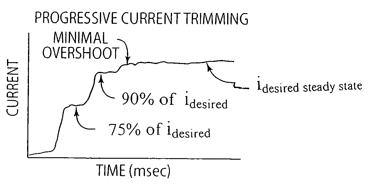
[0006]The present invention provides a dynamic pressure control system where one or more of the electrical current command signals provided to a variable pressure control solenoid valve is / are progressively trimmed in a manner to improve overall system pressure control performance by improving the overall commanded current response. The system can comprise a transmission pressure control system having a pressure control solenoid valve, such as a fast response proportional variable force solenoid (VFS) valve, used for clutch control (gear change). However, the invention is not limited thereto and can be incorporated in any dynamic pressure control system (hydraulic or pneumatic) requiring high accuracy and precision in system response.
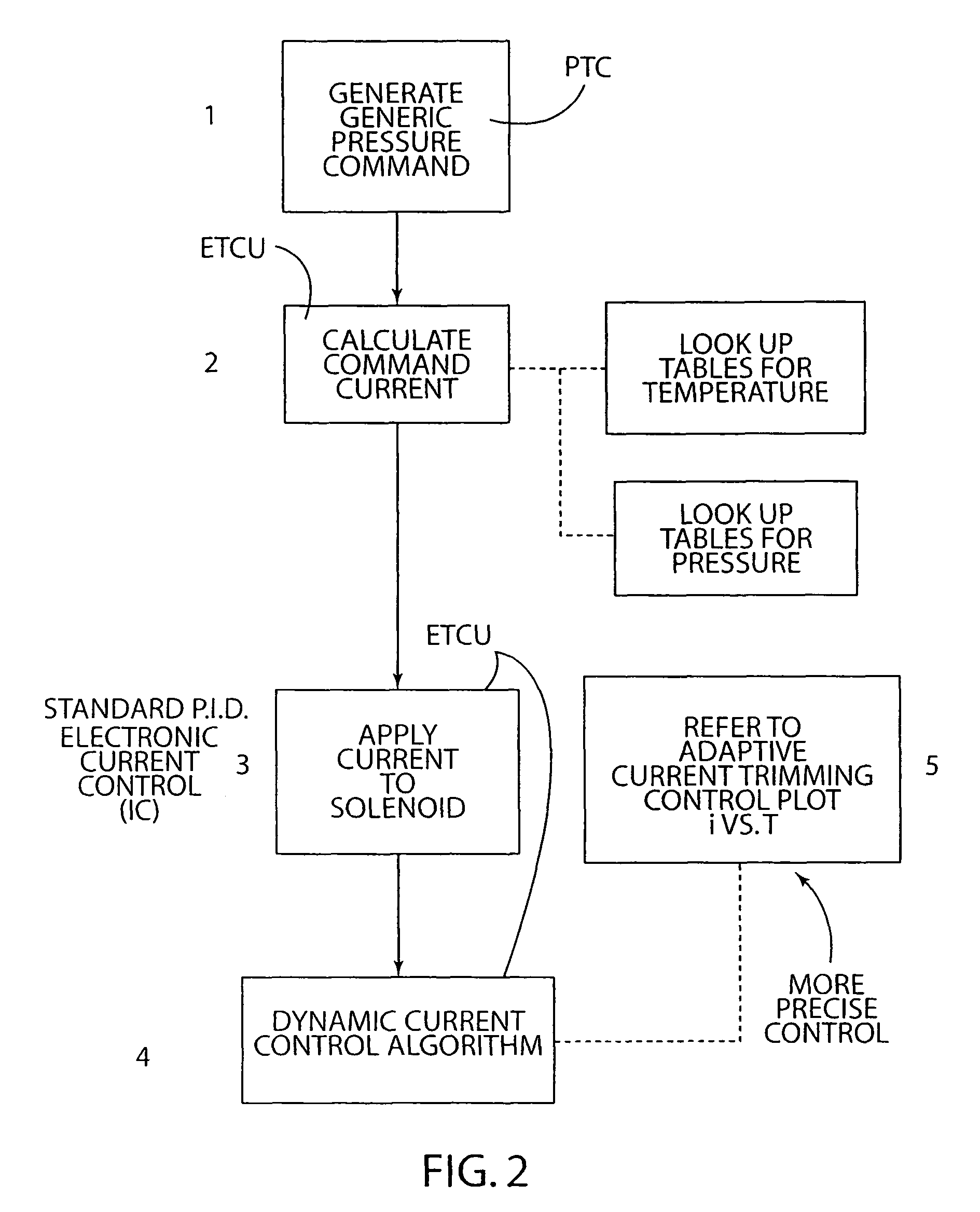
[0007]In an illustrative embodiment of the present invention for a transmission pressure control system including a fast-response pressure control solenoid valve, one or more of the current command signals provided by the ETCU pursuant to a current command control routine is / are progressively trimmed and applied to the control solenoid valve in a manner to minimize overshoot and improve steady state accuracy, so as to thereby improve precision pressure control. For example, in an illustrative working embodiment of the present invention, each total required original current command signal step value is incremented by a modified current control routine of the ETCU into a series of incremental high speed current command steps (as a percentage of the original current command signal step value) and the newly determined incremental current command steps are progressively commanded at a very high rate to the control solenoid valve to transition the current command up to the desired total required command current signal step value. The result is an accurate steady state current that is dynamically more stable (i.e. having lower overshoots) than that provided by a conventional P.I.D. control strategy. In practice of the present invention, the number of incremental current command steps and their amplitudes (e.g. % of original current command step) can be selected so as to tailor the system response to particular dynamic system conditions.

Problems solved by technology

Such systems are complex and require extensive tuning for transient response due to the inherent dynamic variation of the hydraulic system coupled with the inductive loads of the generic solenoids used, generally 35 mH solenoid valve devices.
As a result, overall system response is less than favorable due to the limitations of ETCU response and accuracy as well as generic solenoid dynamic response.
The Table below shows the difficulty of tuning the system response and also the limited tuneability of the three parameters, because rise times, overshoot values, and steady state errors are all affected and are interrelated by the coefficients.
This situation is even further complicated when an extremely fast-responding pressure control solenoid valve is installed in the hydraulic system.
As a result, the improved response of the high speed solenoid valve actually yields less favorable performance (e.g. instability and commanded pressure error) due to the limitations of the ETCU current control.

Method used


Image

  • Dynamic pressure control system with solenoid valve command current trimming
  • Dynamic pressure control system with solenoid valve command current trimming
  • Dynamic pressure control system with solenoid valve command current trimming

Examples


Embodiment Construction

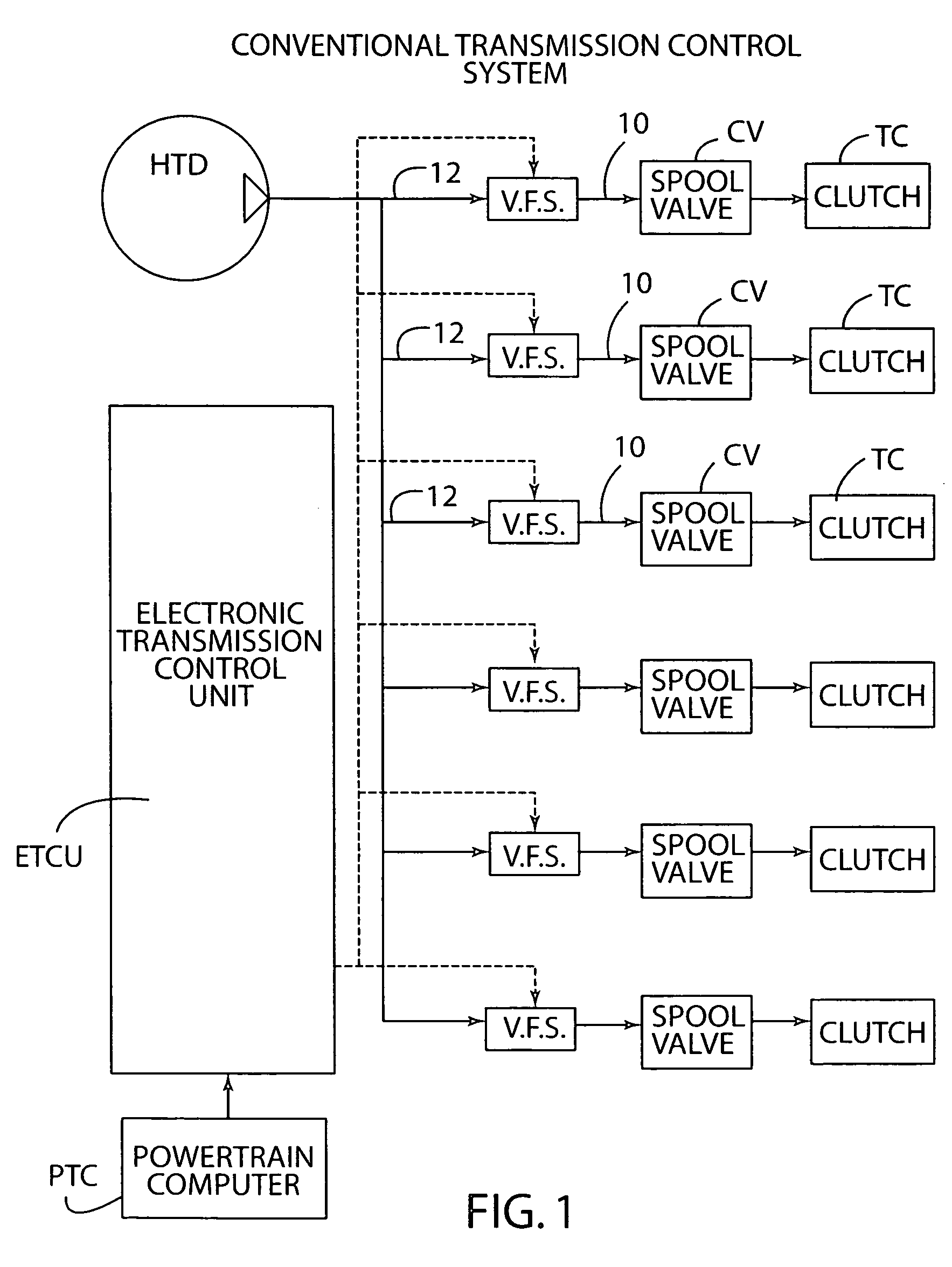
[0016]The present invention will be described herebelow for purposes of illustration with respect to an automatic transmission pressure control system, FIG. 1, having respective fast-response pressure control solenoid valves, such as a proportional variable force solenoid valves V.F.S., used to control respective clutches of the automatic transmission. The present invention is not limited to such pressure control systems and can be practiced to control any dynamic pressure control system (hydraulic or pneumatic) requiring high accuracy and precision in system response.

[0017]Referring to FIG. 1, a transmission pressure control system is shown having a conventional powertrain computer PTC communicated to an electronic transmission control unit ETCU modified in accordance with the present invention, which in turn controls respective fast-response pressure control solenoid valves, such as a proportional variable force solenoid valves V.F.S. The powertrain computer PTC monitors certain v...


PUM


Abstract

A dynamic pressure control system, such as a transmission pressure control system, is provided wherein one or more of electrical current command signals provided to a pressure control solenoid valve, such as a fast response variable force solenoid pressure control valve, are progressively trimmed in a manner to improve overall system pressure control performance by improving the overall commanded current response. The invention permits use of fast response pressure control solenoid valves and obtainment of in a manner to minimize overshoot and improve steady state accuracy, so as to thereby improve precision pressure control.

Description

FIELD OF THE INVENTION[0001]The present invention relates to a dynamic pressure system (hydraulic or pneumatic) where one or more electrical current command signals provided to a variable pressure control solenoid valve is / are subjected to progressive current trimming in a manner to improve overall system pressure control performance by improving the overall commanded current response.BACKGROUND OF THE INVENTION[0002]Advanced pressure control systems are widely used in modern automatic transmission control strategies. For example, U.S. Pat. No. 6,807,472, Closed Loop Control Of Shifting Clutch Actuators In An Automatic Speed Change Transmission, describes an embodiment of pressure control solenoid valves, pressure sensors and an electronic transmission controller (ETCU) to perform closed loop pressure control as function of input current commands derived from the sensor outputs. Such systems are complex and require extensive tuning for transient response due to the inherent dynamic ...

Claims


Application Information

Patent Timeline
Patent Type & Authority Patents(United States)
IPC IPC(8): F16D25/12F16D11/06G06F17/00
CPCF16H61/0251F16H2061/0258F16H2061/0209
Inventor SEID, DAVID L.NAJMOLHODA, HAMID
Owner FLEXTRONICS AUTOMOTIVE USA
Learn More