Liquid jetting head

a liquid jetting head and liquid technology, applied in printing and other directions, can solve the problems of large driving substrate, and large volume of liquid jetting head

Active Publication Date: 2012-05-08
SEIKO EPSON CORP
View PDF10 Cites 6 Cited by
  • Summary
  • Abstract
  • Description
  • Claims
  • Application Information

AI Technical Summary

Benefits of technology

[0007]Accordingly, it is an object of the present invention to provide a liquid jetting head which can contributes to downsizing.
[0009]With such a structure, the driving substrate is arranged in an erect posture on the base surface between the inflow openings of the first and second communication liquid channels provided on the base surface which is located at the opposite side of the nozzle formed-surface of the head unit. Accordingly, it is possible to reduce the horizontal size of the liquid jetting head regardless of the size of the driving substrate. Moreover, with such a structure, there is no need for a through-hole provided to the driving substrate which allows the flexible cable to pass therethrough. Accordingly, it is possible to reduce the size of the driving substrate. Furthermore, unlike the known structure, with such a structure, there is no need to bend the flexible cable when wiring the flexible cable and the driving substrate. Accordingly, it becomes easy to wire the flexible cable and the driving substrate.
[0011]According to the structure, the driving substrate is arranged at the center portion. With such a structure, it is possible to suppress fluctuation of lengths of the wirings, each is connected between the driving substrate and each of the pressure generating chambers, for every pressure generating chamber in comparison with the structure in which the driving substrate is arranged at a position other than the center portion, and it is also possible to suppress fluctuation of electric resistances of the wirings. Thanks to such a structure, fluctuation of a voltage of the driving signal which drives the pressure generating unit decreases. As a result, it is possible to reduce the range of fluctuation of the amount of liquid jetted from each nozzle orifice.
[0012]Further, thanks to the structure in which the communication liquid channels are arranged at both sides of the driving substrate arranged at the center portion of the base surface, the whole size of the liquid jetting head can be reduced in comparison with a structure in which the communication liquid channels are arranged at any one side of the driving substrate.
[0013]Furthermore, since there is no need for a clearance hole, through which the channel passes and which is provided to the wiring substrate like the known structure, it is possible to reduce the chance that a short-circuited state occurs at the time of liquid leakage which is likely to occur.
[0017]According to the structure, the driving substrate is held in the substrate holding portion of the liquid introducing member and the introducing portion of the liquid supply path is arranged at one side of the driving substrate in a widthwise direction thereof. Accordingly, it is possible to stably arrange the driving substrate in an erect posture and it is possible to adopt a layout in which the driving substrate and the liquid supply path are separated from each while suppressing the increase of the size of the liquid jetting head in a direction perpendicular to the surface of the driving substrate. With such a structure, it becomes possible to reduce the chance of the short-circuited state which is likely to occur.

Problems solved by technology

For such a reason, a size of the driving substrate in a plan view increases, resulting in a large driving substrate.
As a result, a problem, in which the entire volume of the liquid jetting head increases, arises.

Method used


Image

  • Liquid jetting head
  • Liquid jetting head
  • Liquid jetting head

Examples


Embodiment Construction

[0030]Hereinafter, preferred embodiments for practicing the invention will be described with reference to the accompanying drawings. In the following embodiments, various kinds of limitation are given as concrete examples. However, the scope of the invention is not limited to those aspects as long as there is no particular description of the effect that the examples limit the invention in the following explanation. In the embodiments, an ink jet-type recording head (hereinafter, referred to as recording head) is disclosed as an example of a liquid jetting head.

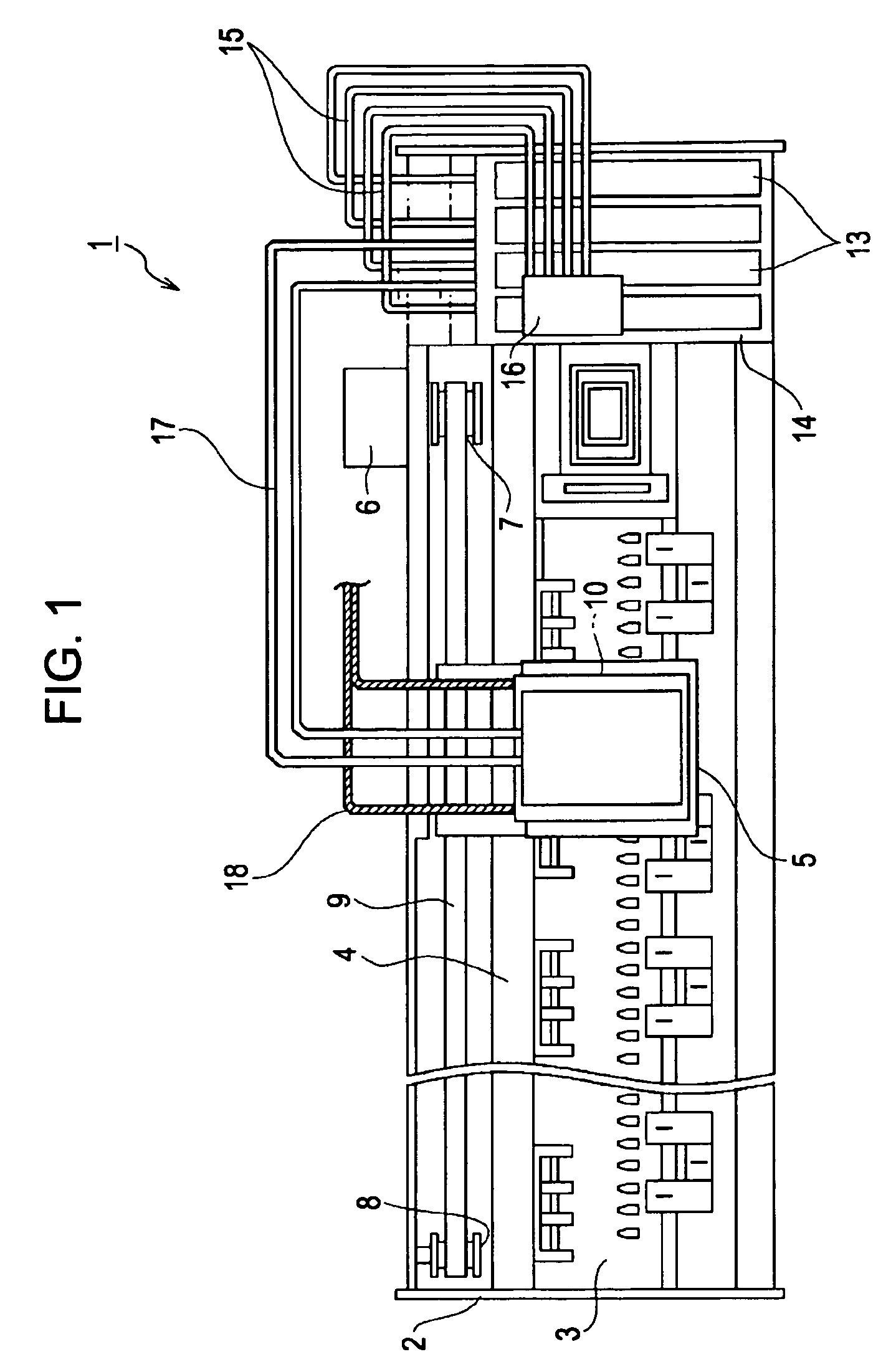
[0031]FIG. 1 is a plan view showing a structure of a printer 1 on which a recording head 10 according to the invention is mounted. The printer 1 includes a frame 2 and a platen 3 arranged in the frame 2 and is structured in a manner such that recording paper (recording medium or one kind of jetting object, not shown) on the platen is transported by a paper sending roller (not shown) which rotates as a paper sending motor drive...


PUM


Abstract

Disclosed is a liquid jetting head which can contribute to downsizing. A head unit 20 has two case channels and a driving substrate 28 arranged between inflow openings 35 of the case channels provided on a base surface of the head unit, which is on the opposite side of a nozzle-formed surface of the head unit, in an erect posture with respect to the base surface of the driving substrate 28.

Description

[0001]The present invention contains subject matters related to Japanese Patent Application No. 2007-208838 and Japanese Patent Application No. 2008-192198 filed in the Japanese Patent Office on Aug. 10, 2007 and Jul. 25, 2008, respectively, the entire contents of which are incorporated herein by reference.BACKGROUND OF THE INVENTION[0002]The present invention relates to a liquid jetting head, such as an ink jet-type recording head, and more particularly to a liquid jetting head having a head unit, which is capable of jetting liquid contained in a liquid containing chamber from nozzle orifices by driving pressure generating units, and a driving substrate, which supplies the pressure generating units with a driving signal.[0003]A representative of a liquid jetting head which can jet (discharges) liquid may be an ink jet-type recording head (hereinafter, referred to as recording head) which is mounted in an ink jet-type printer (a kind of liquid jetting apparatus, hereinafter referred...

Claims


Application Information

Patent Timeline
Patent Type & Authority Patents(United States)
IPC IPC(8): B41J2/14B41J2/045B41J2/175
CPCB41J2/14274B41J2/175B41J2/17509B41J2002/14362
Inventor AKAHANE, FUJIO
Owner SEIKO EPSON CORP
Why Eureka
Try Eureka