Adjustable decking system for supporting freight

a technology of supporting freight and adjustable decking, which is applied in the direction of loading/unloading vehicle arrangment, transportation items, load accommodation, etc., can solve the problems of wasting considerable time and cost, and the use of existing tools saves considerable time and cost in providing a newly designed tool. , to achieve the effect of saving considerable time and cos

Active Publication Date: 2012-05-08
ANCRA INTERNATIONAL CORPORATON
View PDF16 Cites 43 Cited by
  • Summary
  • Abstract
  • Description
  • Claims
  • Application Information

AI Technical Summary

Benefits of technology

[0009]The present invention provides an improved configuration for use in a system generally similar to the structure of the system described in U.S. Pat. No. 6,074,143. The improved configuration provides an improved design of the tab on the lock keys to allow more forceful manipulation thereon than the manual manipulation minimum force by a person's thumb or finger to release the latching fingers from engagement in the apertures and also provide a downward force on the tab to move the guide shoes to the desired height for the shelving. A specially configured tool for the manipulation of the tab on the lock keys is provided. The specifically configured tool, according to the principals of the present invention, is one that has been hereto for utilized in some applications in attempts to move the tab on the lock keys so as to release the shoes and thereby allow the structure to move by gravity to the desired height. However, applying a downward force on the guide shoes to move the guide shoes to a new desired location was often not possible due to the design of the tab. By re-configuring the tab, the existing tool may be utilized to both move the tab to release the shoes as well as to apply a downward force thereon. The use of the existing tool saves considerable time and cost in providing a newly designed tool.
[0014]According to the principles of the present invention, the tab on the lock keys of the guide shoes is formed in the shape of a hook having the opening thereof facing the track. A tool member is provided for selectively engaging the hook to move the hook pivotally away from the track against the force of a biasing spring to release the latching fingers from the apertures in the track. In the hook engaged position, the tool can also provide a downwardly directed force on the hook shaped tab to move the guide shoes downwardly on the track This allows the guide shoes to move along the track to any desired height. The tool allows exertion of a much greater force on the tab than the manual manipulation minimum force exerted by a person's thumb or finger as previously utilized in the prior art.

Problems solved by technology

However, applying a downward force on the guide shoes to move the guide shoes to a new desired location was often not possible due to the design of the tab.
The use of the existing tool saves considerable time and cost in providing a newly designed tool.

Method used


Image

  • Adjustable decking system for supporting freight
  • Adjustable decking system for supporting freight
  • Adjustable decking system for supporting freight

Examples


Embodiment Construction

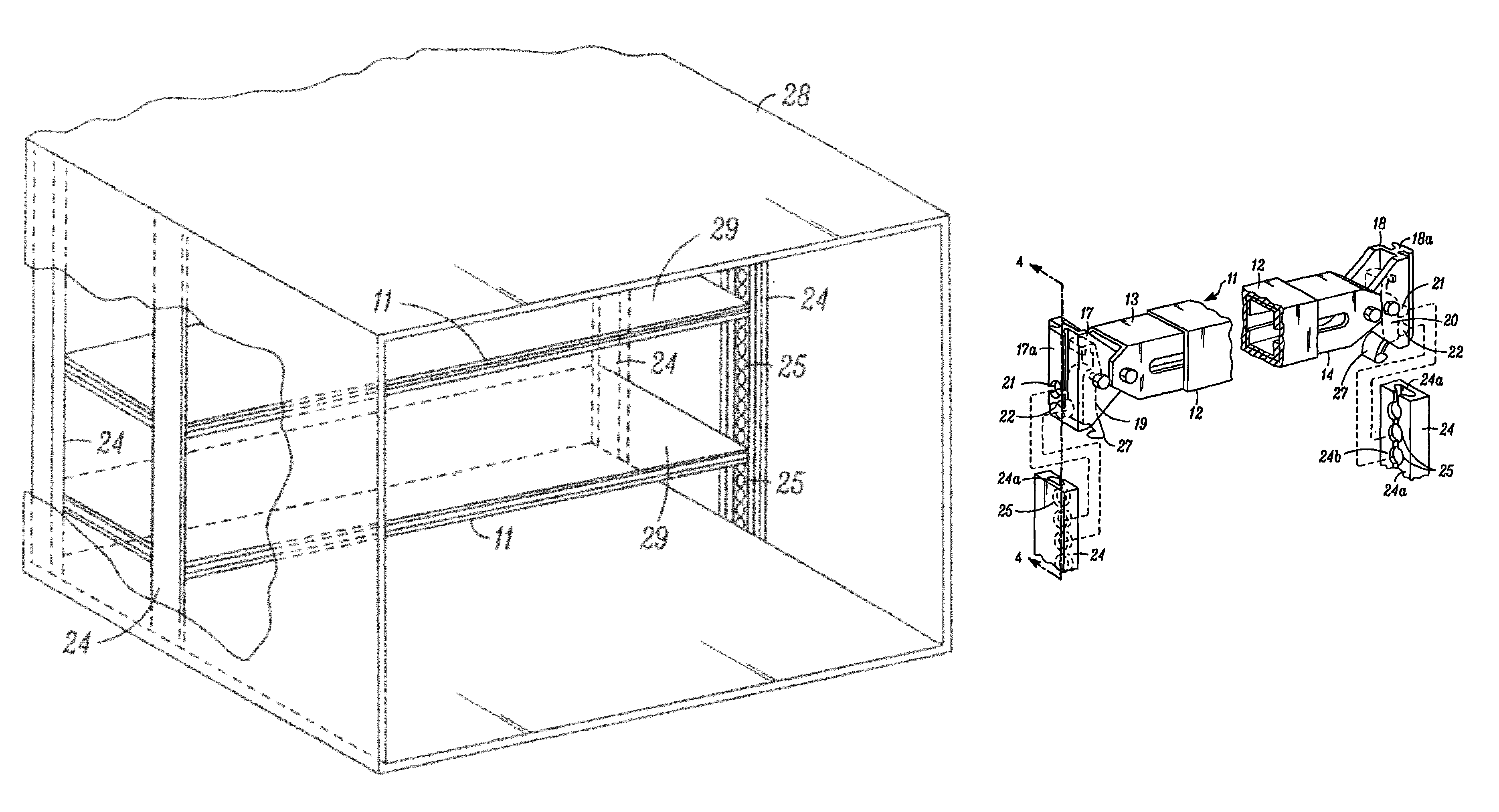
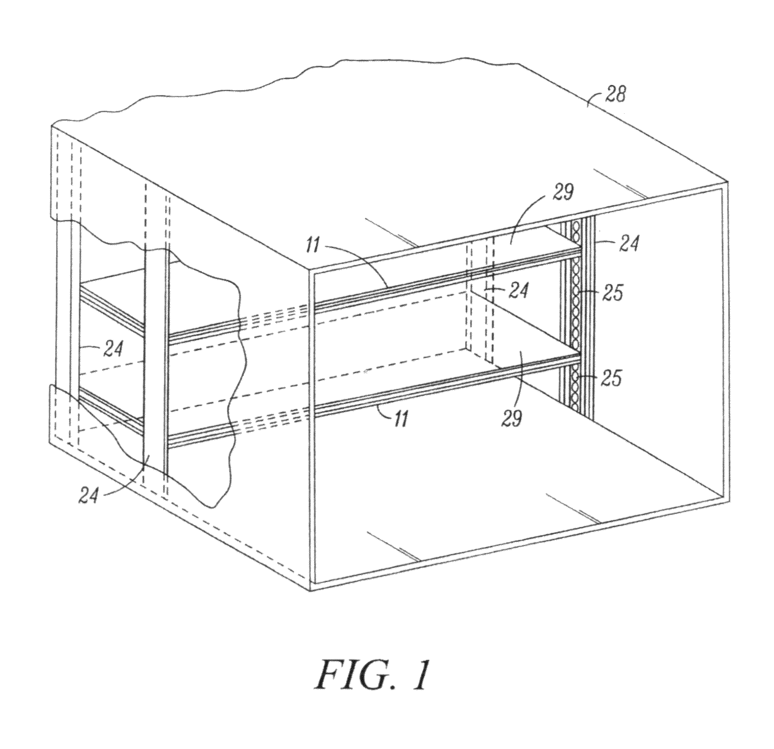
[0033]Referring now to FIG. 1, there is shown a perspective view of a system in which the present invention may be advantageously utilized. Two pairs of tracks 24 are mounted on the side walls of compartment 28, the tracks of each pair being directly opposite each other. Compartment 28 may be the freight carrying compartment of a vehicle such as a truck. The tracks have spaced openings 25 formed therein, these openings being arranged along the longitudinal extent of the tracks.

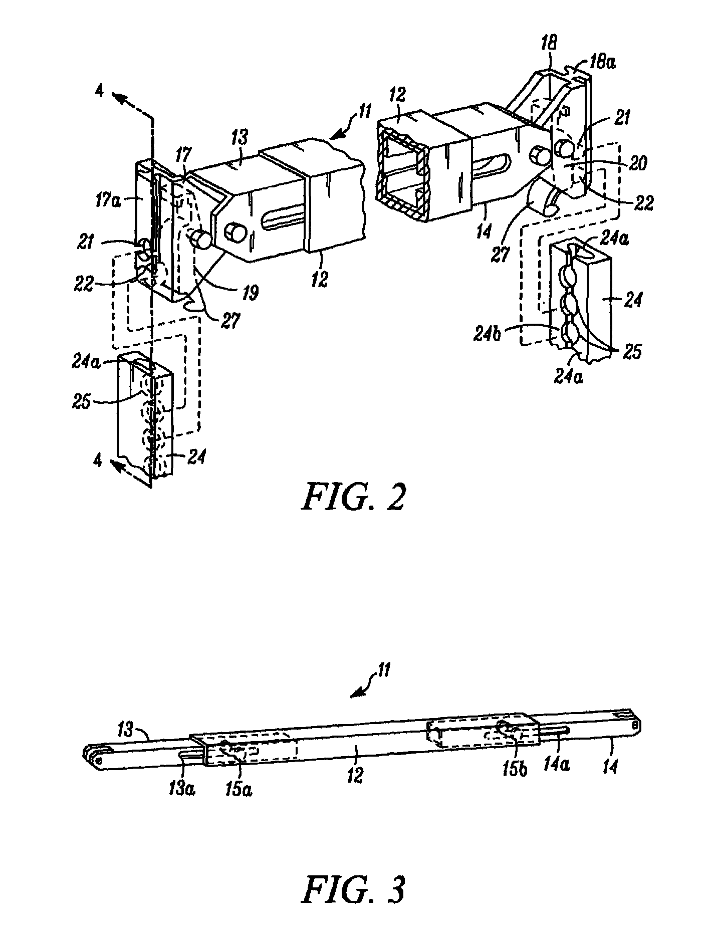
[0034]Supported between tracks 24 are beam assemblies 11. Such beam assemblies, as to be described in detail further on in the specification, can be adjusted to a desired height in engagement with a pair of opposing tracks 24 at a selected pair of track openings 25. By setting a pair of such beams in the forward and rear tracks at the same height, a support for shelves 29 is provided. If so desired, the shelving can be dispensed with and the beam assemblies used to directly support cargo containers or the like...


PUM


Abstract

A beam assembly is formed from a hollow beam member which has a pair of slidable channel units installed therein and extend from the opposite ends thereof. The ends of the channel units have guide shoes forming latching assemblies pivotally supported thereon, each guide shoe having a spring loaded lock key mounted pivotally mounted thereon. A pair of tracks are spaced from each other in opposing relationship by a distance equal to the longitudinal extent of the beam member. The tracks have a plurality of aligned apertures and C-shaped runners running along their longitudinal extent. The lock keys of the beam member each has a pair of latching fingers extending therefrom which fit into a pair of adjacent track apertures. The latching fingers may be locked in place in the opposing track apertures by the spring action of their associated springs and may be withdrawn from the apertures by way of a hook shaped tab attached thereon. A tool is provided to move the hook shaped tabs away from the track to release the latching fingers from engagement with the apertures in the track and, is desired to move the hook shaped tabs downwardly to move the guide shoes downwardly to a desired location on the track. The guide shoes further have T-shaped portions which engage the C-shaped runners of the tracks to retain the guide shoes on the tracks for vertical movement. A pair of the beam members may thus be raised and lowered on the track and provide support for pallets, planking or the like.

Description

BACKGROUND OF THE INVENTION[0001]1. Field of the Invention[0002]This invention relates to decking systems in which the deck height can be adjusted and more particularly to such a system for use in supporting freight in a vehicle compartment and to improved method and apparatus for adjusting the deck height.[0003]2. Description of the Prior Art[0004]In vehicles employed for handling freight such as trucks, aircraft and railroad cars, it is often desirable to provide beams, decks, or shelves to support various cargo items. In order to facilitate loading and unloading of such cargo, it is desirable that such cargo support systems be versatile in their positioning and readily relocated from the cargo handling area to a stowage location if need be. In U.S. Pat. No. 5,338,137, inventor: Richard H. Jensen, issued Aug. 16, 1994 and assigned to Ancra International, LLC, the assignee of the present application, a decking system is described which employs paired beams for supporting a shelf or...

Claims


Application Information

Patent Timeline
Patent Type & Authority Patents(United States)
IPC IPC(8): B60P7/00
CPCB60P1/00B60P7/15
Inventor KNOX, HOWARD T.
Owner ANCRA INTERNATIONAL CORPORATON
Why Eureka
Try Eureka