
Optical encoder comprising a main and reference light receiving portions with a three-phase signal generation for detecting displacement and direction of displacement of an incremental grating track

a technology of optical encoder and reference light, which is applied in the direction of navigation instruments, instruments for comonautical navigation, instruments, etc., can solve the problems of spoiled encoder performance, difficult to separate reference marks to detect reference points, and difficult to set up, so as to reduce light quantity, reduce cost, and improve robustness

Active Publication Date: 2012-05-08
MITUTOYO CORP
View PDF13 Cites 6 Cited by
  • Summary
  • Abstract
  • Description
  • Claims
  • Application Information

AI Technical Summary

Benefits of technology

The present invention provides an optical encoder with a small-sized detector that can detect reference points accurately. The optical encoder includes a scale with an incremental track and a detection portion that is displaced relative to the scale. The optical encoder also includes a light irradiation portion, a main light receiving portion, and a reference signal light receiving portion. A reference mark can be formed on the scale or integrated with the phase grating of the incremental track. The light source can be a point light source or a spatial filter. The width of the reference mark, the main light receiving portion, and the reference signal light receiving portion can be set up to meet certain requirements. The signal processing portion can include a pulse interval detection circuit, a delay circuit, and a circuit for storing the light-receiving level of the reference signal. The present invention allows for downsizing of the detection portion and improved accuracy of reference detection.

Problems solved by technology

In an incremental type optical encoder, it becomes difficult to separate a reference mark to detect a reference point from the incremental track of the main scale where the detector is downsized and the detection range is narrowed.
Provisionally, even if the separation thereof is enabled in a minute range, it becomes difficult to set up (to adjust the alignment of) the detector, wherein the encoder performance is spoiled.
Also, where the incremental track is separated from the reference mark so as to ensure the separation, it becomes difficult to configure the detector to a downsized scale.
However, in this case, signals are subjected to fluctuation in the incremental detection at the reference mark portion, and incremental signals of the main scale are subjected to deterioration in the short range accuracy and a counting error, wherein it becomes difficult to synchronize the reference signal with the incremental signal.
However, since it is necessary to widely take the detection range in order to increase the averaging effect, it is difficult to downsize the detector.
Also, since the incremental signal of the main scale is broken, there are problems that it becomes difficult to secure strict reference synchronization.

Method used


Image

  • Optical encoder comprising a main and reference light receiving portions with a three-phase signal generation for detecting displacement and direction of displacement of an incremental grating track
  • Optical encoder comprising a main and reference light receiving portions with a three-phase signal generation for detecting displacement and direction of displacement of an incremental grating track
  • Optical encoder comprising a main and reference light receiving portions with a three-phase signal generation for detecting displacement and direction of displacement of an incremental grating track

Examples


embodiment 1

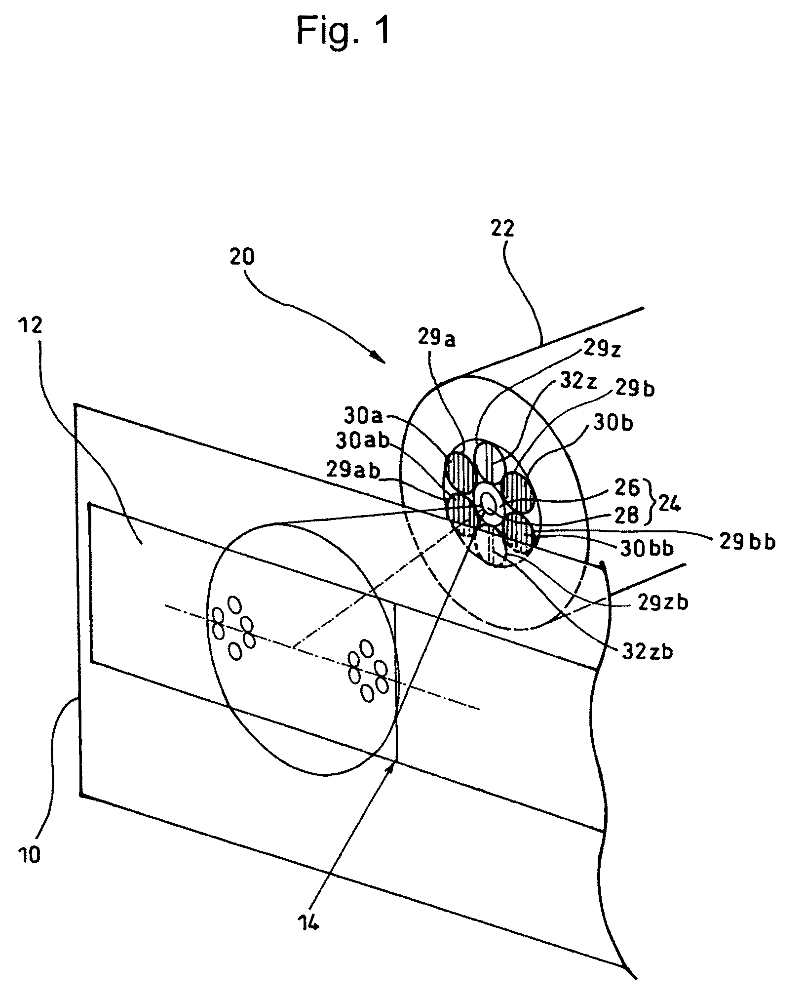
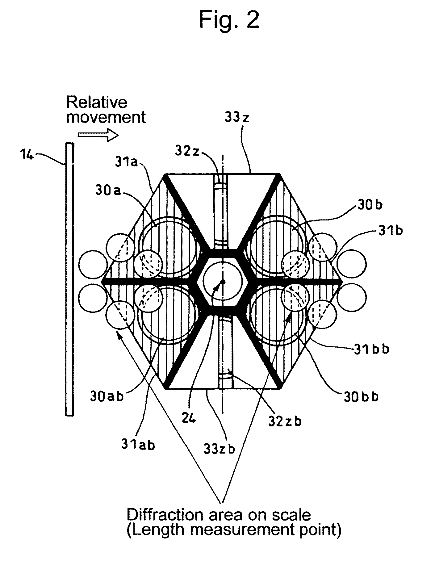
[0048]The configuration of scale 10 and detector 20 of the present invention is shown in FIG. 1 (Perspective view) and FIG. 2 (Plan view observed from the scale side).

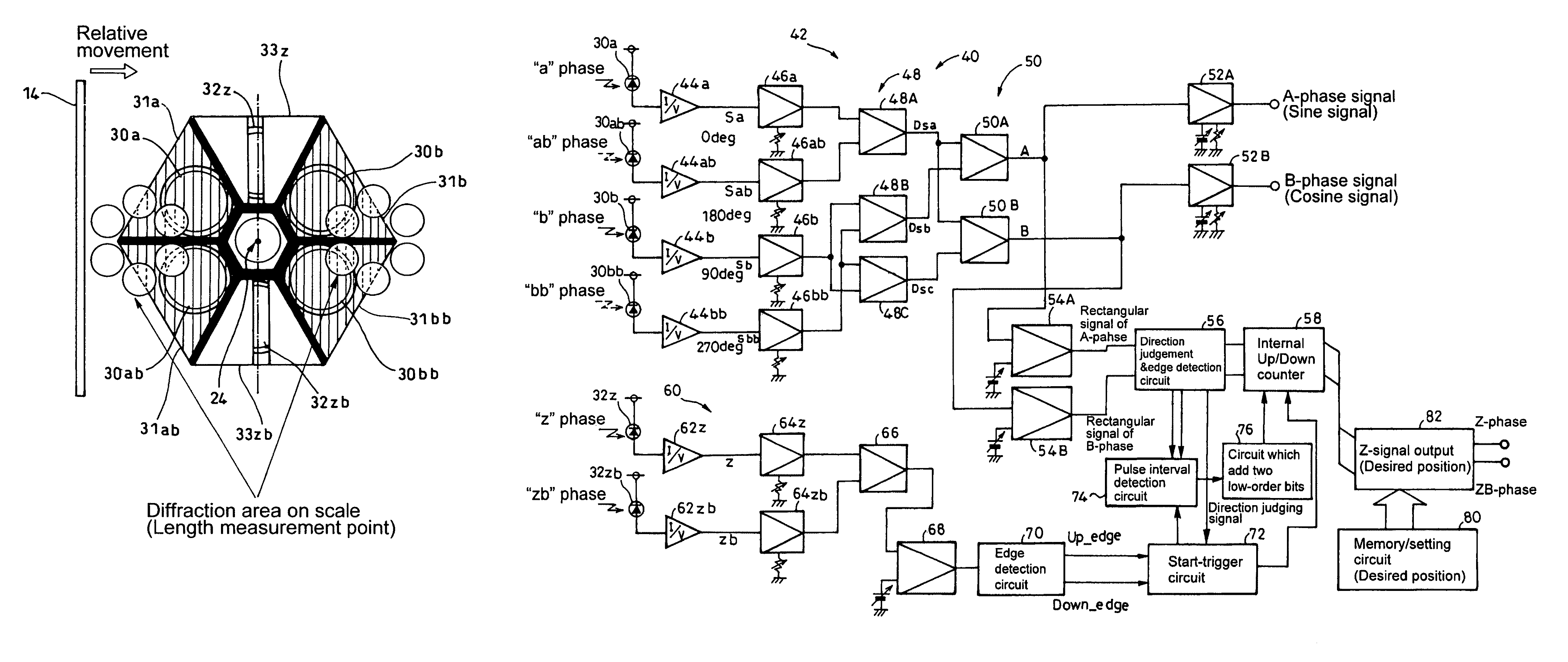
[0049]As shown in detail in FIG. 3, the scale 10 includes incremental tracks 12 composed of a reflective phase grating and a reference mark 14 composed of a reflection slit parallel to the phase grating of the incremental track 12, which is formed at an end portion detectable by the detector 20 on at least one point of the incremental track 12, for example, outside the length measurement range. The corresponding a reference mark 14 may be made into an integrated grating structure as shown in, for example, FIG. 4(a), or may be made into an add-on structure as shown in FIG. 4(b). Here, the width W0 of the reference mark 14 is approximately half the width Wz (Refer to FIG. 5) of light-receiving differential slits 33z, 33zb of the reference light receiving portions 32z, 32zb as shown in FIG. 2, and is a width required so ...

embodiment 2

[0098]In addition, shown in FIG. 18, where a level value memory circuit 67 is provided in the output of the above-described “z” phase / “zb” phase differential amplifier 66, and the level is used for the judgment level of the comparator 68, it will be possible to further accurately detect the reference regardless of deterioration in the light source, changes in the reflection ratio due to staining on the surface and / or oxidation.

[0099]Also, in the above-described embodiments, although optical fibers are used for the detector, the present invention is applicable not only to the same but also to a configuration of the detector composed of, for example, a light-emitting diode and a photodiode or a photodiode array, etc.


PUM


Abstract

In an optical encoder for measuring relative displacement, a scale 10 has a reference mark 14 composed of a reflection slit formed on at least one point of an incremental track 12, a detection portion (20) has a light irradiation portion (24), main light receiving portions 30a, 30b, 30ab and 30bb that are disposed at the surrounding centering around the corresponding light irradiation portion and output incremental signals four phases of which are different from each other, and a pair of reference signal light receiving portions 32z and 32zb that are disposed in the direction perpendicular to the length measurement direction using the light irradiation portion as the center of point symmetry, and a signal processing portion 40 has a three-phase signal generation portion 48, a quadrature sine wave signals generation portion 50, a direction judgment circuit 56, an internal period counter 58, and a reference signal processing portion 60, thereby bringing about a micro-sized optical encoder capable of detecting the reference.

Description

CROSS-REFERENCE TO RELATED APPLICATION[0001]The disclosure of Japanese Patent Application No. 2008-240216 filed on Sep. 19, 2008 including specifications, drawings and claims is incorporated herein by reference in its entirety.BACKGROUND OF THE INVENTION[0002]1. Field of the Invention[0003]The present invention relates to an optical encoder, and in particular to an optical encoder, which is preferably used as a length measurement sensor such as a laser interferometer, etc., including: a main scale having an incremental track with a reflective phase grating formed along the length measurement direction; and a detection portion that is displaced relative to the main scale.[0004]2. Description of the Related Art[0005]In an incremental type optical encoder, it becomes difficult to separate a reference mark to detect a reference point from the incremental track of the main scale where the detector is downsized and the detection range is narrowed. Provisionally, even if the separation the...

Claims


Application Information

Patent Timeline
Patent Type & Authority Patents(United States)
IPC IPC(8): G01D5/34G01D5/36
CPCG01D5/38
Inventor TAKAHASHI, TOMOTAKA
Owner MITUTOYO CORP
Learn More