

Optical encoder
a technology of optical encoder and encoder, which is applied in the direction of navigation instruments, instruments for comonautical navigation, instruments, etc., can solve the problems of spoiled encoder performance, difficult to separate reference marks to detect reference points, and difficult to set up, so as to reduce light quantity, improve robustness, and low cost
- Summary
- Abstract
- Description
- Claims
- Application Information
AI Technical Summary
Benefits of technology
Problems solved by technology
Method used
Image

Examples
embodiment 1
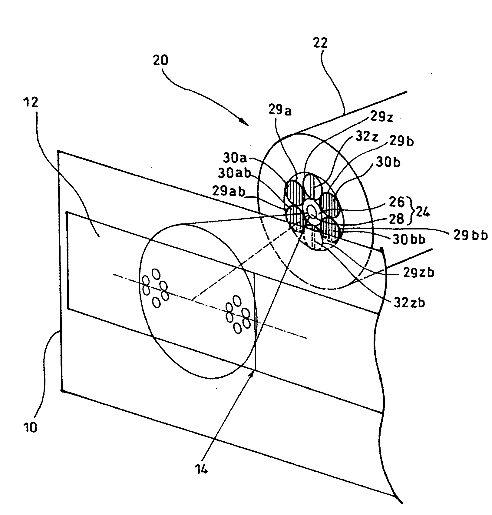
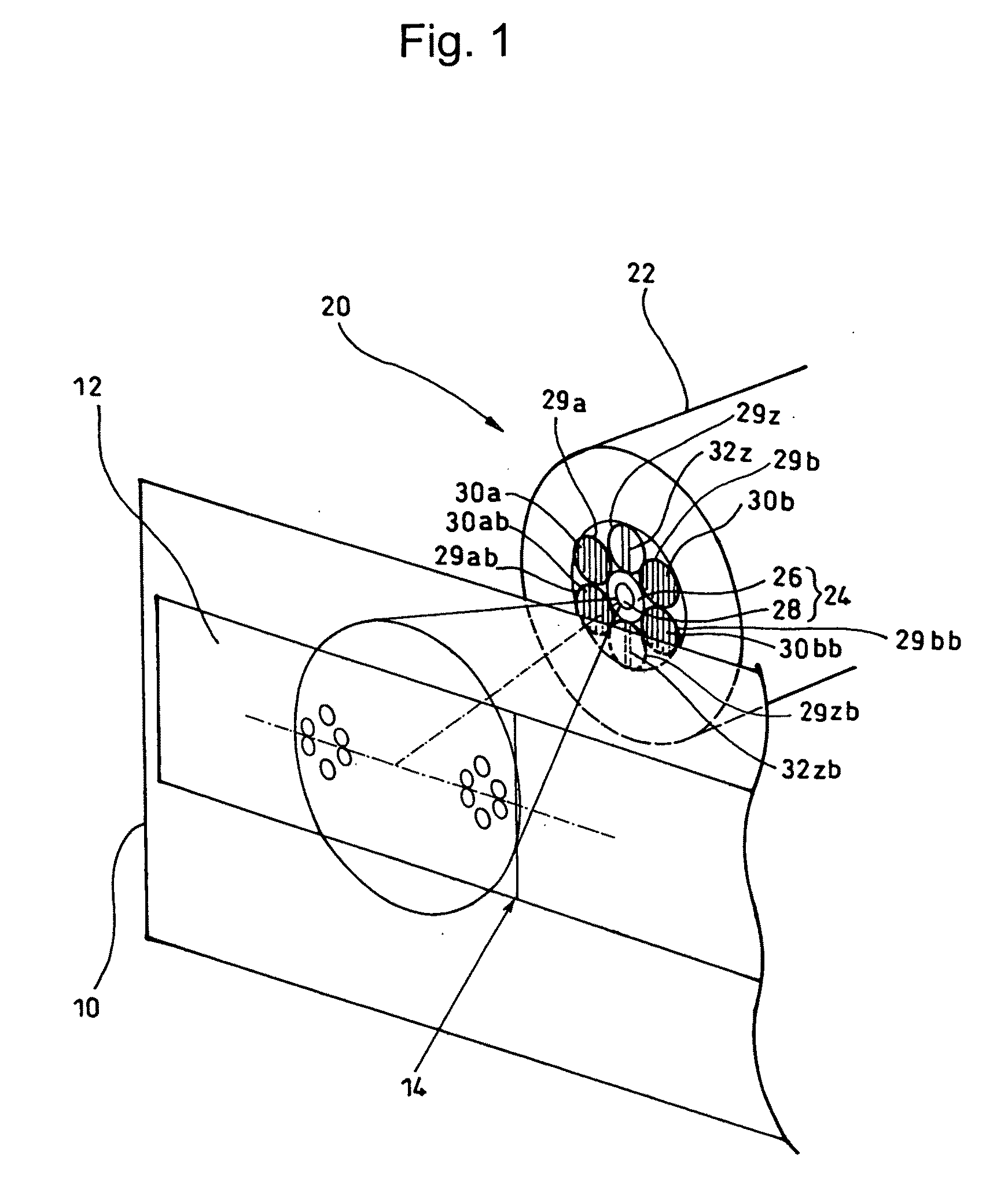
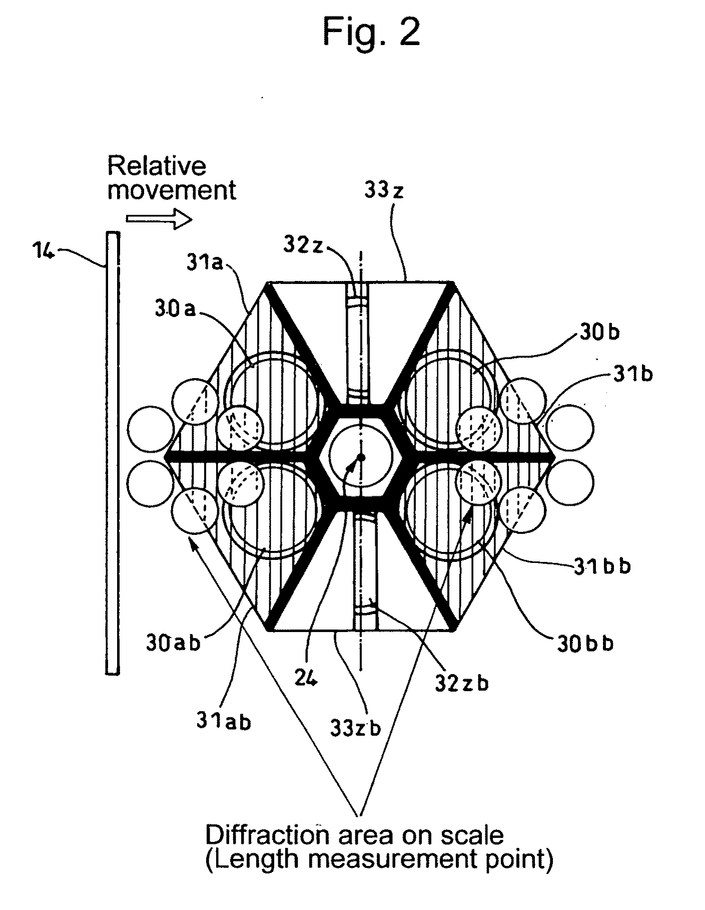
[0048]The configuration of scale 10 and detector 20 of the present invention is shown in FIG. 1 (Perspective view) and FIG. 2 (Plan view observed from the scale side).
[0049]As shown in detail in FIG. 3, the scale 10 includes incremental tracks 12 composed of a reflective phase grating and a reference mark 14 composed of a reflection slit parallel to the phase grating of the incremental track 12, which is formed at an end portion detectable by the detector 20 on at least one point of the incremental track 12, for example, outside the length measurement range. The corresponding a reference mark 14 may be made into an integrated grating structure as shown in, for example, FIG. 4(a), or may be made into an add-on structure as shown in FIG. 4(b). Here, the width W0 of the reference mark 14 is approximately half the width Wz (Refer to FIG. 5) of light-receiving differential slits 33z, 33zb of the reference light receiving portions 32z, 32zb as shown in FIG. 2, and is a width required so ...
embodiment 2
[0098]In addition, shown in FIG. 18, where a level value memory circuit 67 is provided in the output of the above-described “z” phase / “zb” phase differential amplifier 66, and the level is used for the judgment level of the comparator 68, it will be possible to further accurately detect the reference regardless of deterioration in the light source, changes in the reflection ratio due to staining on the surface and / or oxidation.
[0099]Also, in the above-described embodiments, although optical fibers are used for the detector, the present invention is applicable not only to the same but also to a configuration of the detector composed of, for example, a light-emitting diode and a photodiode or a photodiode array, etc.
PUM
 Abstract
Description
Claims
Application Information