
Image processor and image display apparatus comprising the same

a technology of image processor and image display apparatus, which is applied in the direction of signal generators with optical-mechanical scanning, television systems, color signal processing circuits, etc., can solve problems such as erroneous detection of motion vectors, and achieve the effect of less jitter or breakage, and high picture quality images

Active Publication Date: 2012-05-08
MAXELL HLDG LTD
View PDF17 Cites 11 Cited by
  • Summary
  • Abstract
  • Description
  • Claims
  • Application Information

AI Technical Summary

Benefits of technology

The present invention provides a frame conversion technology that can display high quality images even when there is a change in brightness in certain areas of the image. By designating specific areas with a change in brightness and acquiring motion vectors for those areas, the technology can accurately detect and match motion between frames. This results in a smooth and jitter-free image, even for image patterns where change in brightness occurs periodically or non-periodically.

Problems solved by technology

Consequently, a number of pixel pairs having the minimum difference appear in the predetermined area, causing erroneous detection of a motion vector.
Therefore, a detection error occurs by regarding one of the sticks in the previous frame has moved to the adjacent stick in the subsequent frame.

Method used


Image

  • Image processor and image display apparatus comprising the same
  • Image processor and image display apparatus comprising the same
  • Image processor and image display apparatus comprising the same

Examples


embodiment i

[Embodiment I]

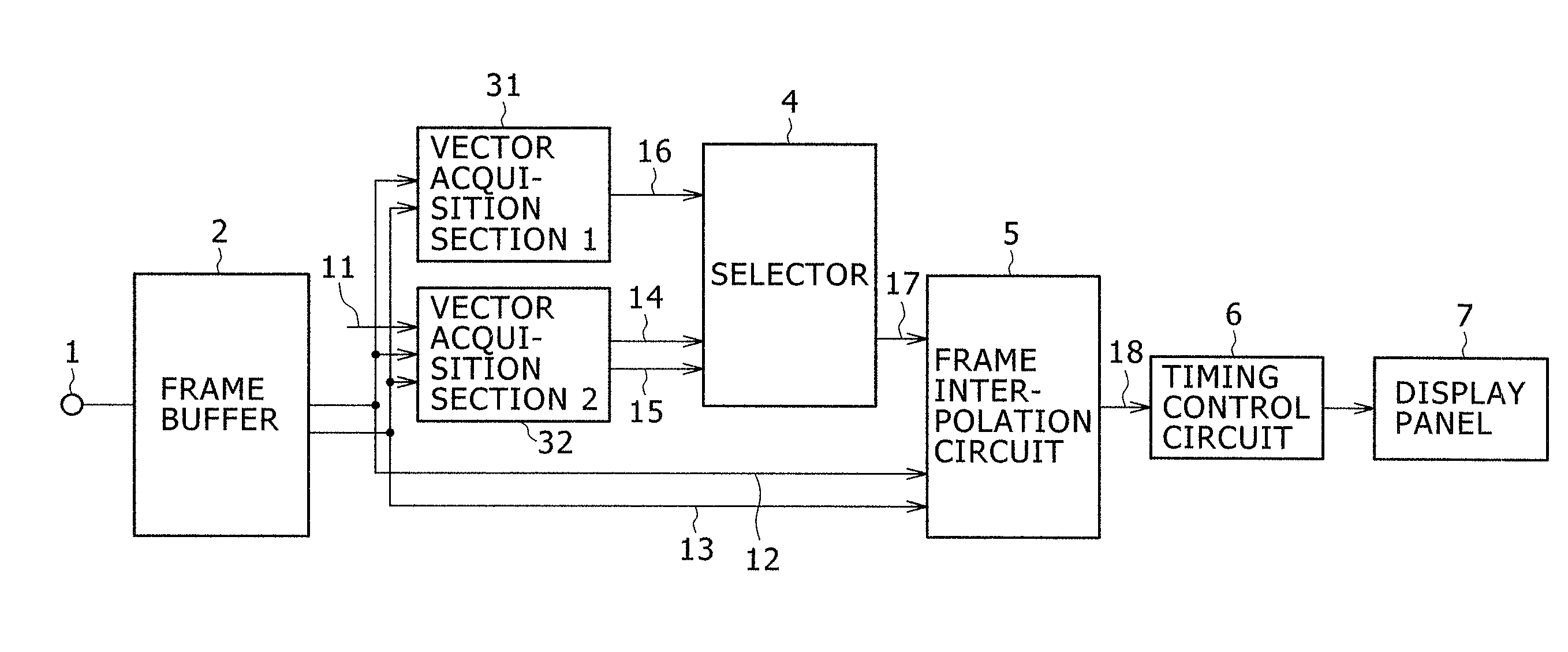
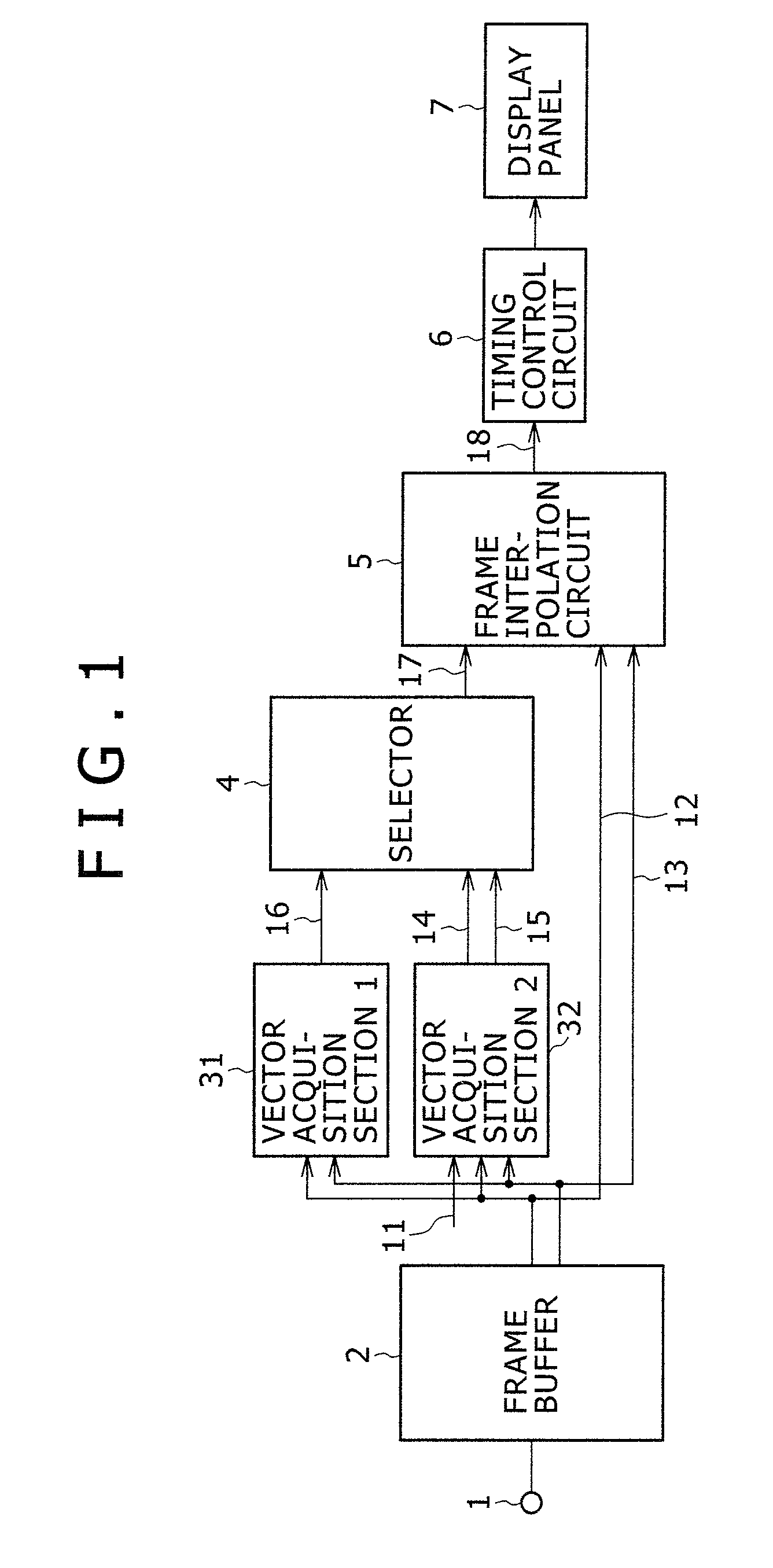
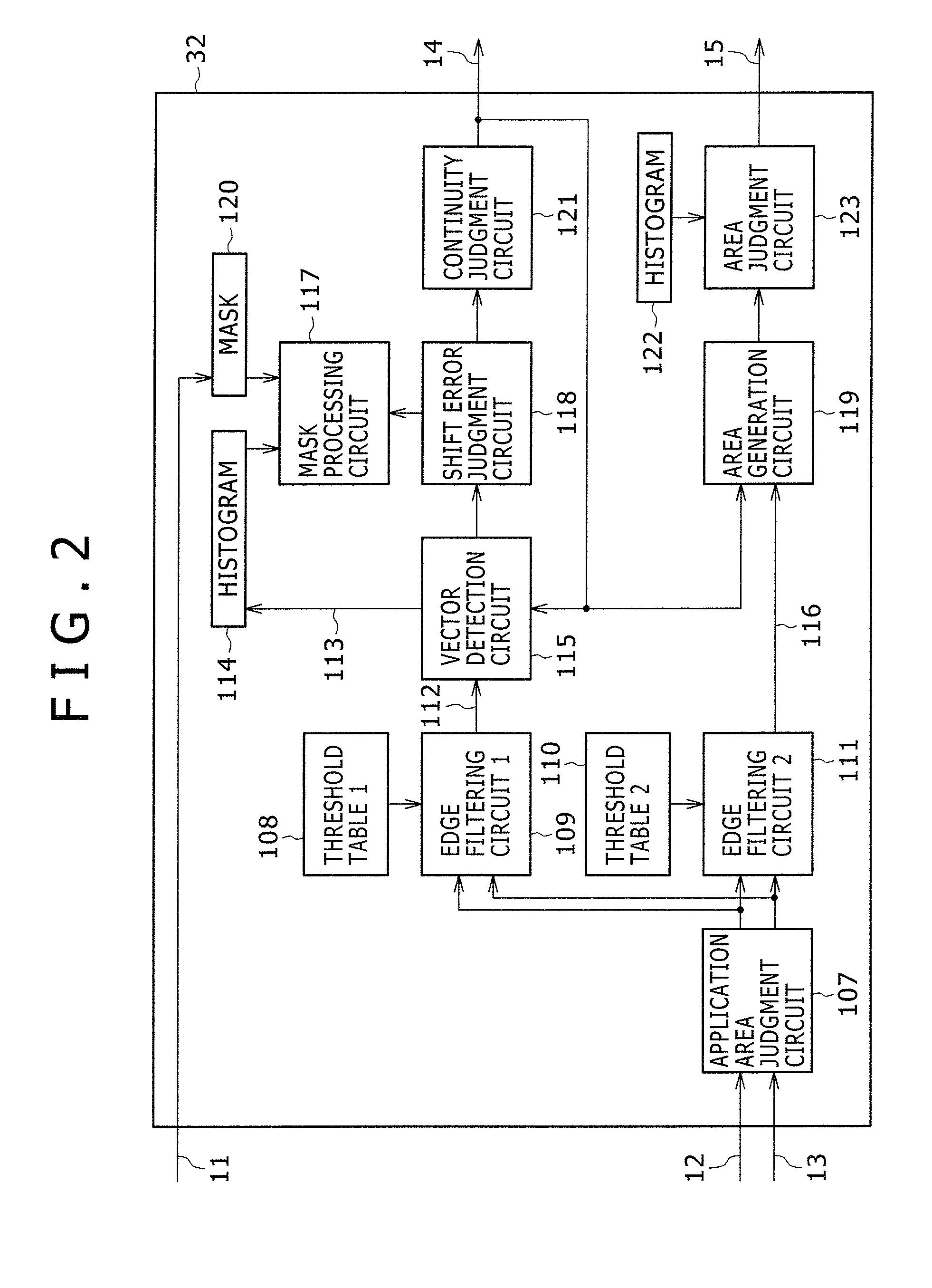
[0033]A first embodiment of the invention will be described with reference to FIGS. 1 and 2. FIG. 1 shows an image processor according to a first embodiment of the present invention, or a structural view of one example of an image display apparatus having a display panel 6 to which the present invention is applied.

[0034]An image signal is inputted to an input terminal 1, and frame data corresponding to at least two of the input image signals is stored in a frame buffer 2. Accordingly, the frame buffer 2 outputs a previous frame 12 that is temporally ahead and a subsequent frame 13 that is temporally behind the previous frame. The previous frame 12 and the subsequent frame 13 are respectively inputted to a first motion vector acquisition section 31, a second motion vector acquisition section 32, and a frame interpolation circuit 5.

[0035]The first motion vector detection section 31 detects a motion vector by the matching process described above from the previous and subs...

embodiment ii

[Embodiment II]

[0089]A second embodiment of the invention will be described with reference to FIGS. 3 and 4A to 4C. In particular, the second embodiment shown in FIG. 3 is characterized by setting up plural the second motion vector acquisition sections 32 of FIG. 1 in parallel. In FIG. 3, constitutional elements indicated by the same reference numerals used in the first embodiment have the same functions, so details on them are omitted.

[0090]As mentioned above, the second embodiment features the use of a plural number (four to be specific) of the second motion vector acquisition sections 32a to 32d, and a mask synthesis circuit 303 is additionally provided to synthesize and output an output from each. This embodiment enables to generate a second motion vector 14 and an area identification signal 15 for a plurality of specific areas. Even though the second motion vector acquisition sections used in the first and the second embodiment are substantially the same in configuration, they ...


PUM


Abstract

An image processor includes a motion vector acquisition section for acquiring and outputting an image motion vector in pixel or a predetermined block unit from plural frames included in an input image signal; and a frame interpolation section for generating an interpolated frame by using the motion vector provided by the motion vector acquisition section and for combining the interpolated frame with a frame of the input image signal, thereby composing a signal of a new frame sequence. The motion vector acquisition section includes a first motion vector acquisition section acquiring a motion vector by matching process and a second motion vector acquisition section acquiring a motion vector based on a relative misalignment of a predetermined edge component between two temporally successive frames in a specific area of an input image signal's frame.

Description

CLAIM OR PRIORITY[0001]The present application claims priority for Japanese application serial No. JP 2006-353700, filed on Dec. 28, 2006, the content of which is hereby incorporated by reference into this application.BACKGROUND OF THE INVENTION[0002](1) Field of the Invention[0003]The present invention relates to an image processor and an image display apparatus; and, more particularly, to an image processor that includes a configuration for converting frame rate of an input image signal and an image display apparatus.[0004](2) Description of the Related Art[0005]A technique called frame rate conversion has been recently introduced for offering better moving image performance. It uses frames included in an image signal and a motion vector of the input image signal and combines interpolation frames created in an apparatus to generate a signal of a new frame sequence. Accordingly, it becomes possible to offer better moving image performance by improving unnatural motion such as a fee...

Claims


Application Information

Patent Timeline
Patent Type & Authority Patents(United States)
IPC IPC(8): H04J3/06H04N7/01
CPCH04N7/0142
Inventor FUKUDA, NOBUHIROOGINO, MASAHIROMIZUHASHI, YOSHIAKIOYAMA, TAKASHI
Owner MAXELL HLDG LTD
Learn More