Planar heat generating element, fixing device including the same, and image forming apparatus including the same

a technology of fixing device and heat generating element, which is applied in the direction of electrographic process apparatus, instruments, optics, etc., can solve the problems of increasing power consumption, taking longer to warm up, not following the temperature of the fixing roller when a process speed is increased, etc., and achieves the effect of resisting heat generator

Active Publication Date: 2012-05-08
SHARP KK
View PDF14 Cites 20 Cited by
  • Summary
  • Abstract
  • Description
  • Claims
  • Application Information

AI Technical Summary

Benefits of technology

[0015]Accordingly, an object of the invention is to provide a planar heat generating element having a resistance heat generator for generating heat upon a passage of electric current therethrough, in which occurrence of localized excessive heat generation in the resistance heat generator can be prevented. Another object of the invention is to provide a fixing device including the planar heat generating element. Still another object of the invention is to provide an image forming apparatus including the fixing device.

Problems solved by technology

However, in a fixing roller having an elastic layer, the elastic layer can not sufficiently conduct heat, thus, in a case where a heating section is provided inside the fixing roller, there is a problem that a temperature of the fixing roller is not followed when a process speed is increased.
On the other hand, when a diameter of the fixing roller is increased, there is a problem that it takes longer time to warm up or power consumption is increased.
Accordingly, the temperature of the both ends of the planar heat generating element is lower than that of its center part and it is difficult to obtain uniform temperature distribution over the all areas in a width direction.
As a result, when such a fixing device is applied to an image forming apparatus such as a copier and a printer, variance is generated in a toner fixing temperature and the printing quality is deteriorated.
In consequence, since the heat generated from the peeled heat generating line 202 cannot be transmitted to the heat generating substrate, it becomes impossible to apply heat to the fixing belt in such a manner as to render the temperature distribution on the surface thereof uniform.
Furthermore, the excessive heat generation from the bend portion 202b leads to the possibility that the heat generating line 202 suffers from a fracture or the insulating layer 203 catches fire.
As a result, the heat generating line 202 is apt to peel due to the resultant excessive heat generation.

Method used


Image

  • Planar heat generating element, fixing device including the same, and image forming apparatus including the same
  • Planar heat generating element, fixing device including the same, and image forming apparatus including the same
  • Planar heat generating element, fixing device including the same, and image forming apparatus including the same

Examples


example 1

[0127]A fixing device used in Example 1 was the above-described fixing device 70. The fixing device 70 was installed in a copying machine (product name: MX-7000N manufactured by SHARP CORPORATION). The detailed conditions set for Example 1 are as follows.

[0128]

[0129]Used was a fixing roller that has a diameter of 30 mm, in which stainless steel having a diameter of 15 mm was used for a core metal and silicone sponge rubber having thickness of 7.5 mm was used for an elastic layer.

[0130]

[0131]Used was a pressure roller that has a diameter of 30 mm and is made of silicone solid rubber, in which PFA tube having thickness of 30 μm was used for a release layer and a heater lamp having a rated power of 400 W is disposed inside.

[0132]

[0133]Used was a fixing belt in which polyimide having thickness of 70 μm was used for a belt substrate, silicone rubber having thickness of 150 μm was used for an elastic layer, and a PTFE coat having thickness of 30 μm was used for a release layer.

[0134]

[0135...

example 2

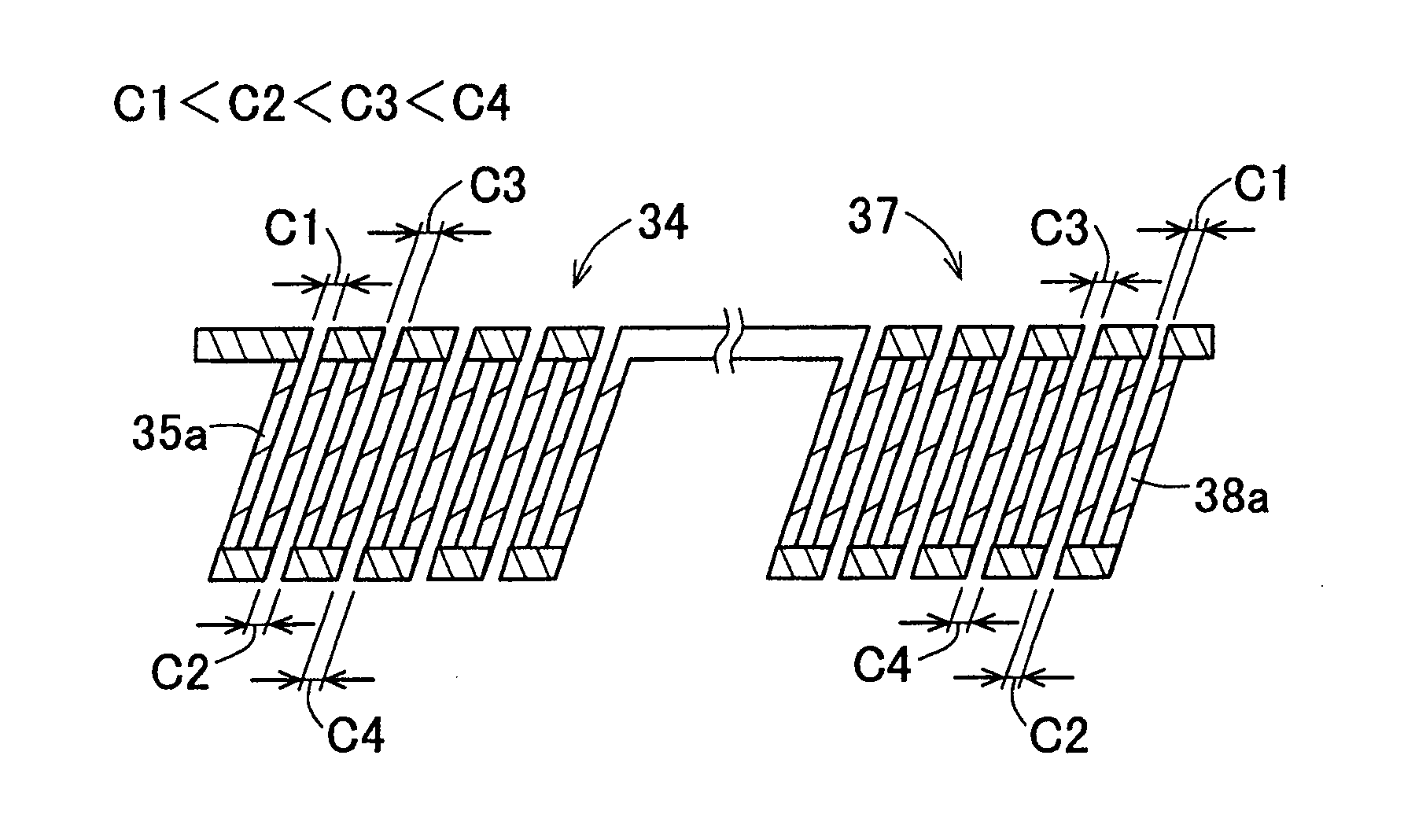
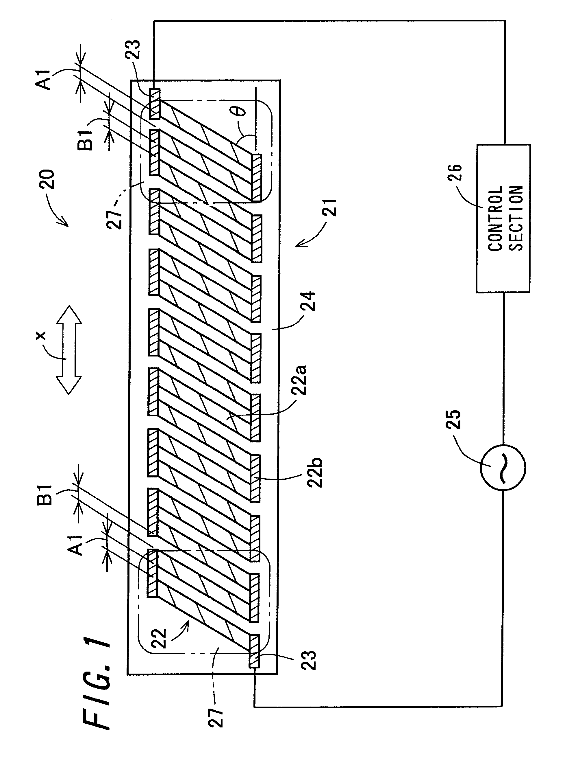
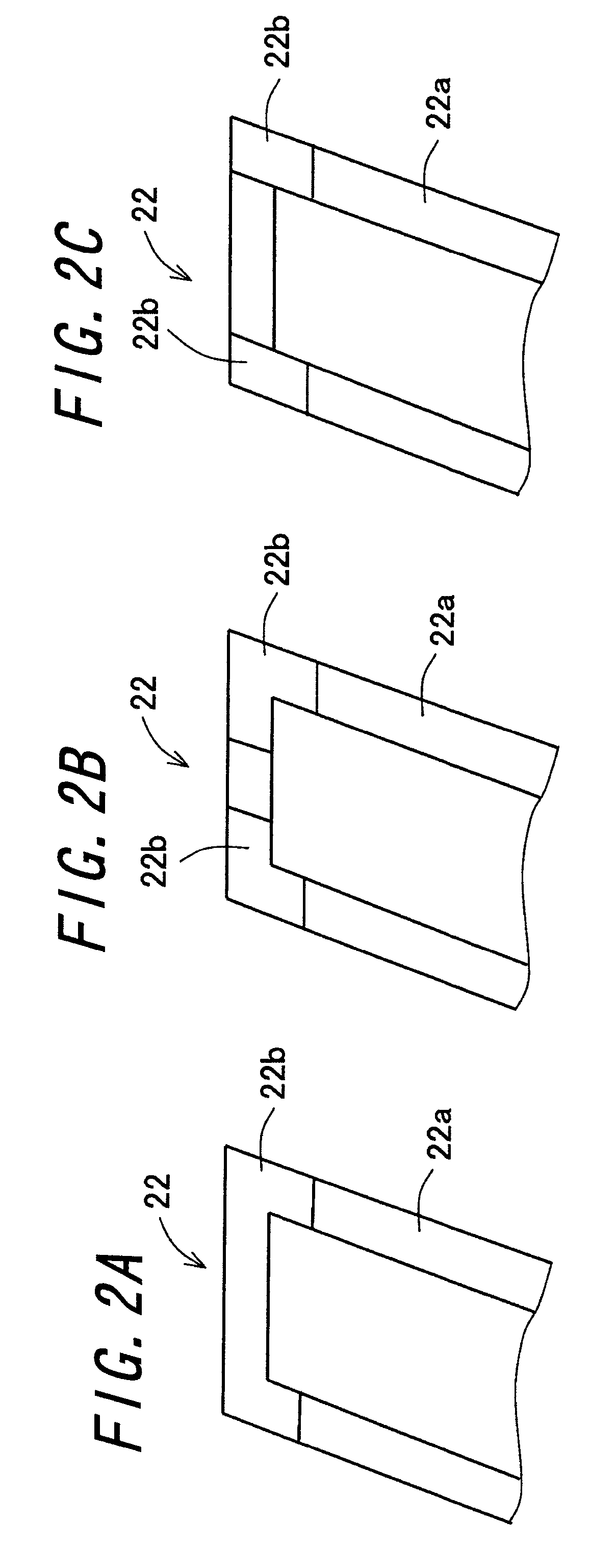
[0152]In Example 2, as the heat generating pattern of the planar heat generating element for use in the heating member, instead of the heat generating pattern 21 of the planar heat generating element 20, the heat generating patterns 31, 34, and 37 of the planar heat generating element 30 were employed. Otherwise, Example 2 has the same structure as that of Example 1.

[0153]Note that the resistance heat generator is 6.6 mm in width. In order to determine the interval between the adjacent linear portions and the inclination angle θ of the linear portion, firstly the width, length, and film thickness of the linear portion to be placed have been estimated on the basis of the amount of power in the heat generating region, the applied voltage, and the volume resistivity of the resistance heat generator for use. Then, the distribution of the surface temperatures of the fixing belt in the image region was obtained by actual measurement using a radiation thermometer, and the fixability of a f...


PUM


Abstract

A planar heat generating element includes an insulating layer and a resistance heat generator formed on one surface in a thickness direction of the insulating layer, for generating heat under a passage of electric current therethrough, the resistance heat generator constituting a plane of certain configuration as a whole and forming a heat generating pattern. The resistance heat generator includes a plurality of linear portions formed on one surface of the insulating layer that extend transversely with respect to a longitudinal direction of the insulating layer, the linear portions being arranged side by side substantially in parallel to each other; and a low-volume resistivity portion formed on the one surface so as to extend in the longitudinal direction of the insulating layer, and connecting the adjacent linear portions at their extending direction-wise ends to form a single line composed of the adjacent linear portions and the low-volume resistivity portion.

Description

CROSS-REFERENCE TO RELATED APPLICATION[0001]This application claims priority to Japanese Patent Application No. 2008-109603, which was filed on Apr. 18, 2008, the contents of which are incorporated herein by reference in its entirety.BACKGROUND OF THE INVENTION[0002]1. Field of the Invention[0003]The present invention relates to a planar heat generating element having a resistance heat generator for generating heat upon a passage of electric current therethrough, a fixing device including the planar heat generating element, and an image forming apparatus including the fixing device.[0004]2. Description of the Related Art[0005]As a fixing device for use in an electrophotographic image forming apparatus such as a copying machine and a printer, a fixing device of heat-roller fixing type has been in wide use. The fixing device of heat-roller fixing type includes a pair of rollers, a fixing roller and a pressure roller, that are brought into contact with each other under pressure. By mea...

Claims


Application Information

Patent Timeline
Patent Type & Authority Patents(United States)
IPC IPC(8): G03G15/20
CPCG03G15/2053G03G2215/2029
Inventor KAGEYAMA, HIROYUKI
Owner SHARP KK
Why Eureka
Try Eureka