
Loading ledge

a technology of loading ledges and ledges, which is applied in the direction of rigid containers, containers with multiple articles, containers, etc., can solve the problems of high price, damage to adjacent pallets, and prior art clips or other locking means of the straps, so as to reduce the amount of material used, save costs, and reduce the weight

Inactive Publication Date: 2012-05-15
INTER IKEA SYST
View PDF43 Cites 4 Cited by
  • Summary
  • Abstract
  • Description
  • Claims
  • Application Information

AI Technical Summary

Benefits of technology

[0013]When designing new products there are a number of more or less obvious objects. Such objects are e.g. having as low weight as possible, in order to reduce the amount of material used and, thus, to save costs. It is also a general object to be able to produce the products in a simple and reliable way to reduce costs.
[0014]One specific object with the present invention is that the loading ledge should be easy to use. A further object is that the loading ledges should be possible to stack, in order to facilitate transport and storing.
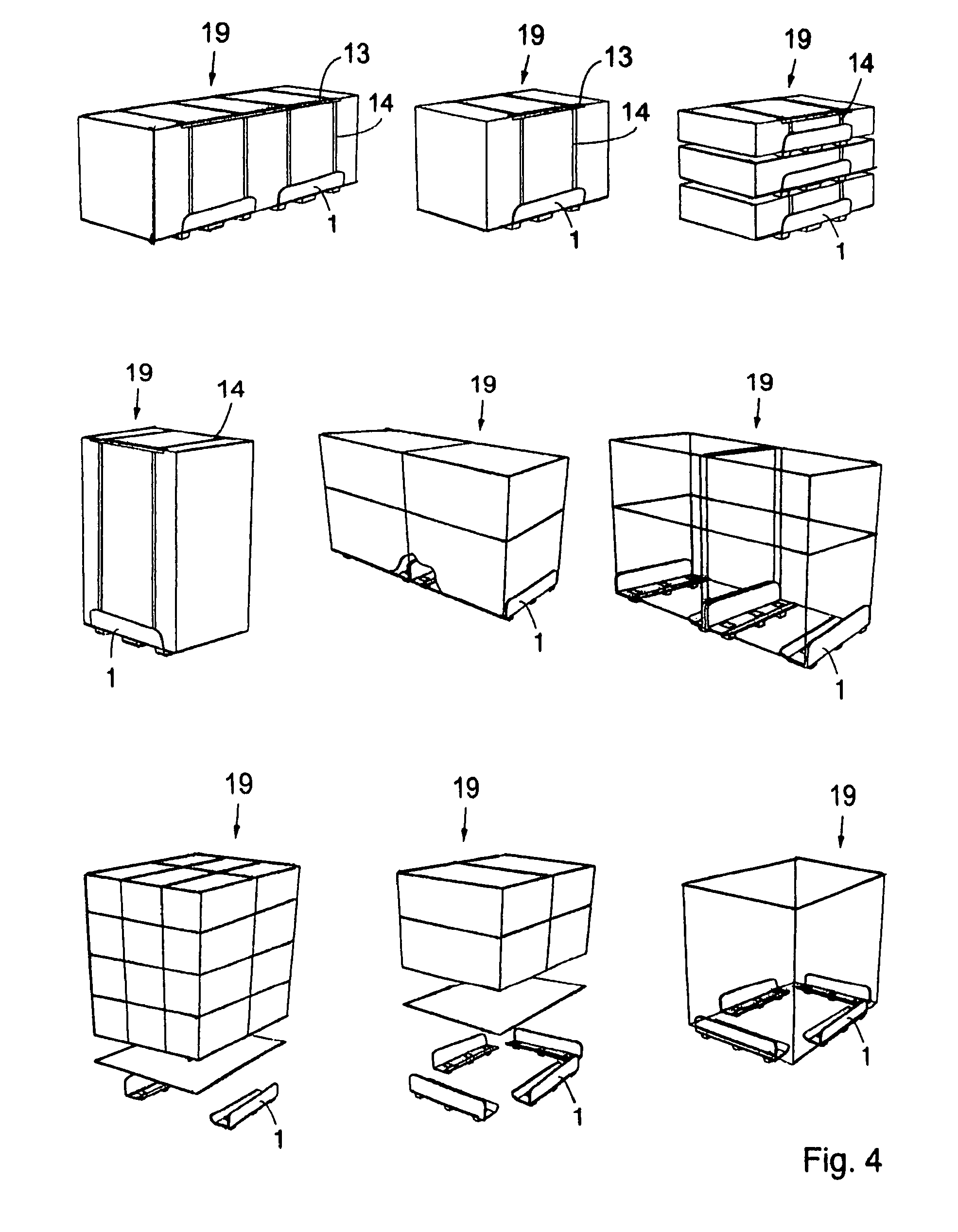
[0017]By using loading ledges according to the present invention for creation of unit loads instead of pallets of a standard dimension the goods it is normally possible to store the goods more compactly. When using standard pallets the total available loading areas are often not used, unless the size of each item of the goods is adapted to the size of the pallets. Furthermore, the loading ledges of the present invention are lower than most standard pallets, increasing the possibility to fully use the available space in containers, trucks, lorries, warehouses etc. Loading ledges according to the present invention are automatically adapted to the dimensions of the unit loads.
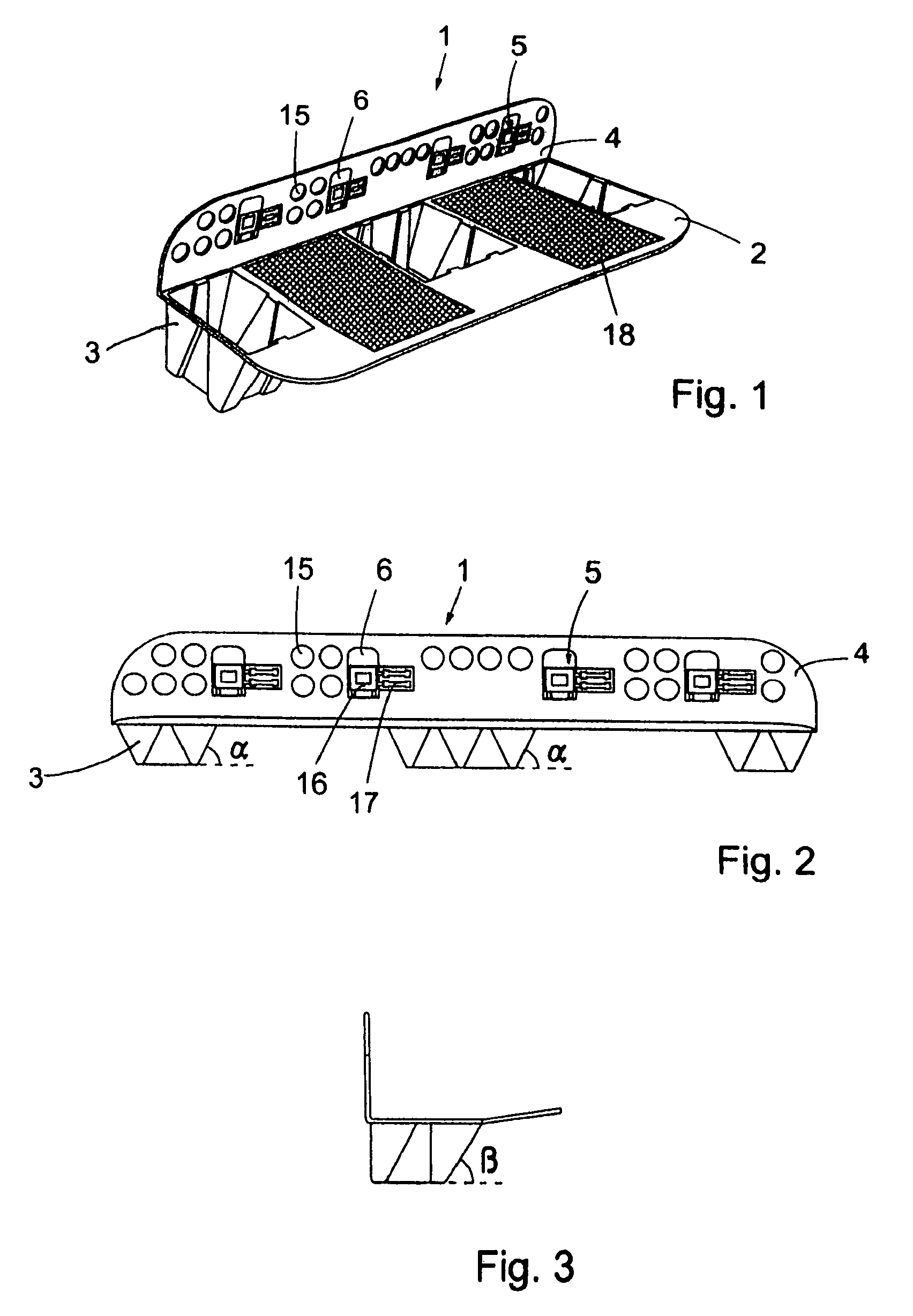
[0018]The weight of the loading ledges are kept as low as possible by providing it with a number of openings, without jeopardising the function. The low weight is beneficial both concerning transport and in that less material is needed to produce each loading ledge.

Problems solved by technology

Further, the tara weight and the price for the loading ledge are very low.
Furthermore, it is a risk that the prior art clips or other locking means for the straps harm goods placed on adjacent pallets, as the locking means normally are placed in varying positions.
Depending on the goods such damages may be serious.

Method used


Image

  • Loading ledge
  • Loading ledge
  • Loading ledge

Examples


Embodiment Construction

[0028]As used in this description the expressions “upper”, “lower” etc. are with reference to loading ledges 1 as shown in the FIGS.

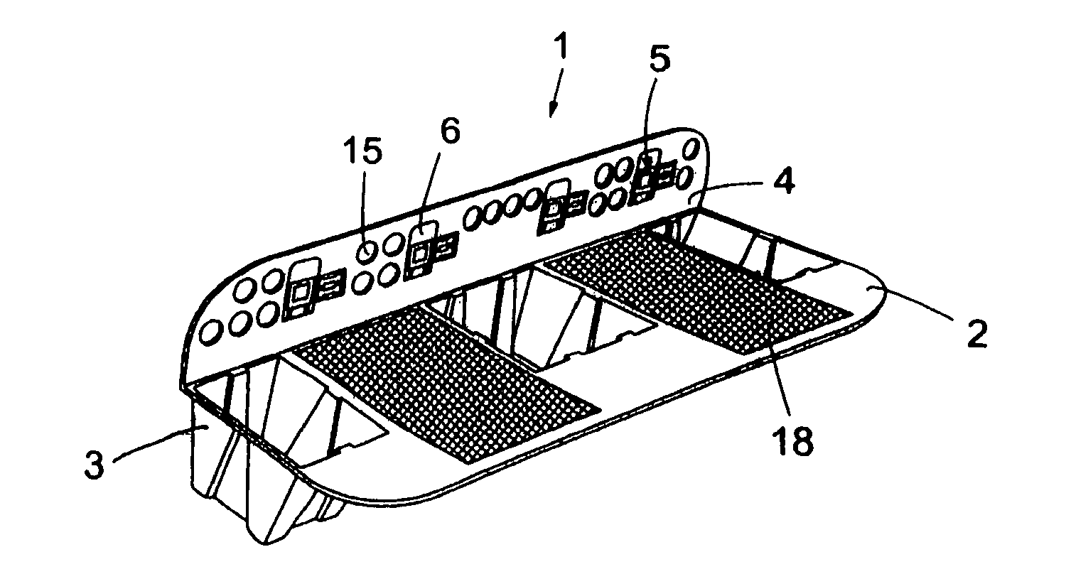
[0029]The present invention concerns loading ledges 1 to be used in transport and storing of goods 19. The loading ledges 1 comprises a lower leg 2 and an upper leg 4, which legs 2, 4 are arranged almost perpendicular to each other. Thus, the loading ledge 1 will have a substantially L-shaped cross section. The loading ledge 1 is preferably an injection moulded, L-shaped profile of recyclable plastic, preferably polypropylene (PP). Its lower leg 2 is provided with projections 3, in the shown case three projections, for supporting a unit load above the ground or other support. The projections 3 make it possible to handle the unit load with ordinary handling equipment utilised for goods on ordinary wooden pallets presently widely used in distribution systems. The upper leg 4 of the loading ledge 1 is generally plain and is to bear against a vertical side ...


PUM


Abstract

A loading ledge to be used in transport and storing and a system for creation of load units. The loading ledge has an upper leg and a lower leg forming a substantially L-shaped cross section. The lower leg is furnished with one or more projections to make it possible to use handling equipment. One or more locking units are integrated in the loading ledge to grip straps or the like. The load unit is created in that two or more loading ledges are used together with straps to fixate the goods on the loading ledges.

Description

[0001]This application is Continuation of U.S. Ser. No. 11 / 083,533, filed 18 Mar. 2005, which is a Continuation Application of PCT / SE2003 / 001437, filed 15 Sep. 2003, which claims benefit of Ser. No. 0202779-5, filed 18 Sep. 2002 in Sweden and which applications are incorporated herein by reference. To the extent appropriate, a claim of priority is made to each of the above disclosed applications.TECHNICAL FIELD[0002]The present invention concerns an improved loading ledge to be used e.g. in transport and storing and a system for creation of load units.PRIOR ART[0003]For transport and storage of different types of goods it is today common to use pallets. Normally wooden pallets of standardized dimensions are used. Often straps and / or stretch or shrink wrapping are wrapped around the pallet including the goods.[0004]Other means for transportation and storage are known, e.g. loading ledges to be placed at the goods. One or more articles are placed on two or more loading ledges to form ...

Claims


Application Information

Patent Timeline
Patent Type & Authority Patents(United States)
IPC IPC(8): B65D19/44B65D19/40B65D19/18B65D19/38B65D71/00
CPCB65D19/385B65D71/0092B65D2571/00086B65D19/18B65D19/38
Inventor DICKNER, ALLAN
Owner INTER IKEA SYST
Learn More