Liquid material application device

a technology of liquid material and application device, which is applied in the manufacture of electric discharge tubes/lamps, basic electric elements, coatings, etc., can solve the problems of increasing the influence of vibration during operation, difficult control of the table, etc., and achieves the effect of maximizing the space within the device, improving the maintainability of the device, and cleaning the environmen

Active Publication Date: 2012-05-15
MUSASHI ENG INC
View PDF13 Cites 6 Cited by
  • Summary
  • Abstract
  • Description
  • Claims
  • Application Information

AI Technical Summary

Benefits of technology

[0026]According to the present invention, since the liquid material application device has the above-described constructions, a compact device can be obtained by effectively utilizing a space within the device.
[0027]Further, since the liquid material application device has the above-described constructions, maintainability of the device can be improved and intrusion of dirt and dust can be cut during the maintenance work, whereby a cleaner environment can be held.

Problems solved by technology

However, a gate type structure has been more popularly used for the reasons that an increase in weight of the table makes it more difficult to control the table and increases the influence of vibrations during the operation.

Method used


Image

  • Liquid material application device
  • Liquid material application device
  • Liquid material application device

Examples


embodiment 1

[0058]>

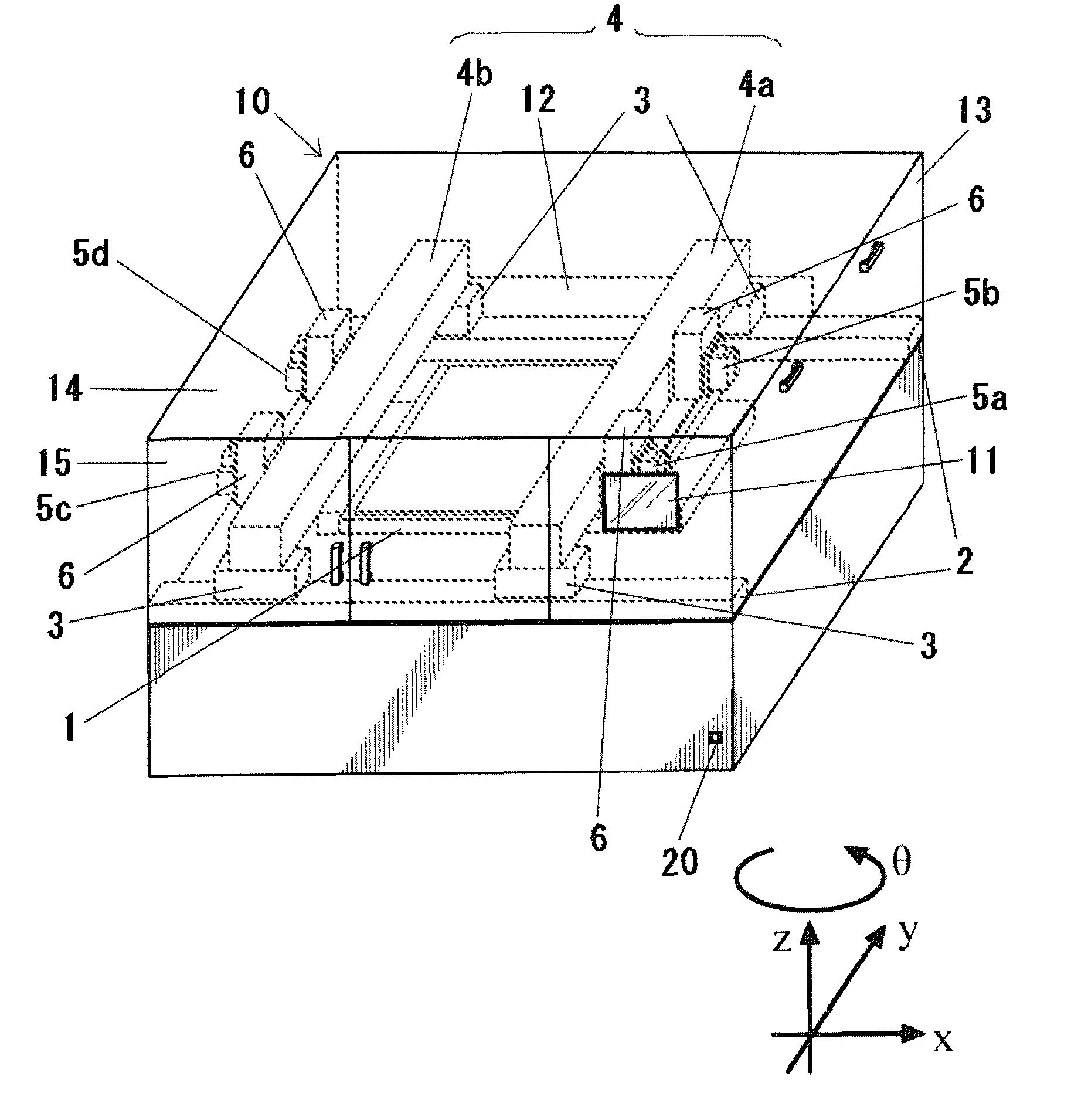
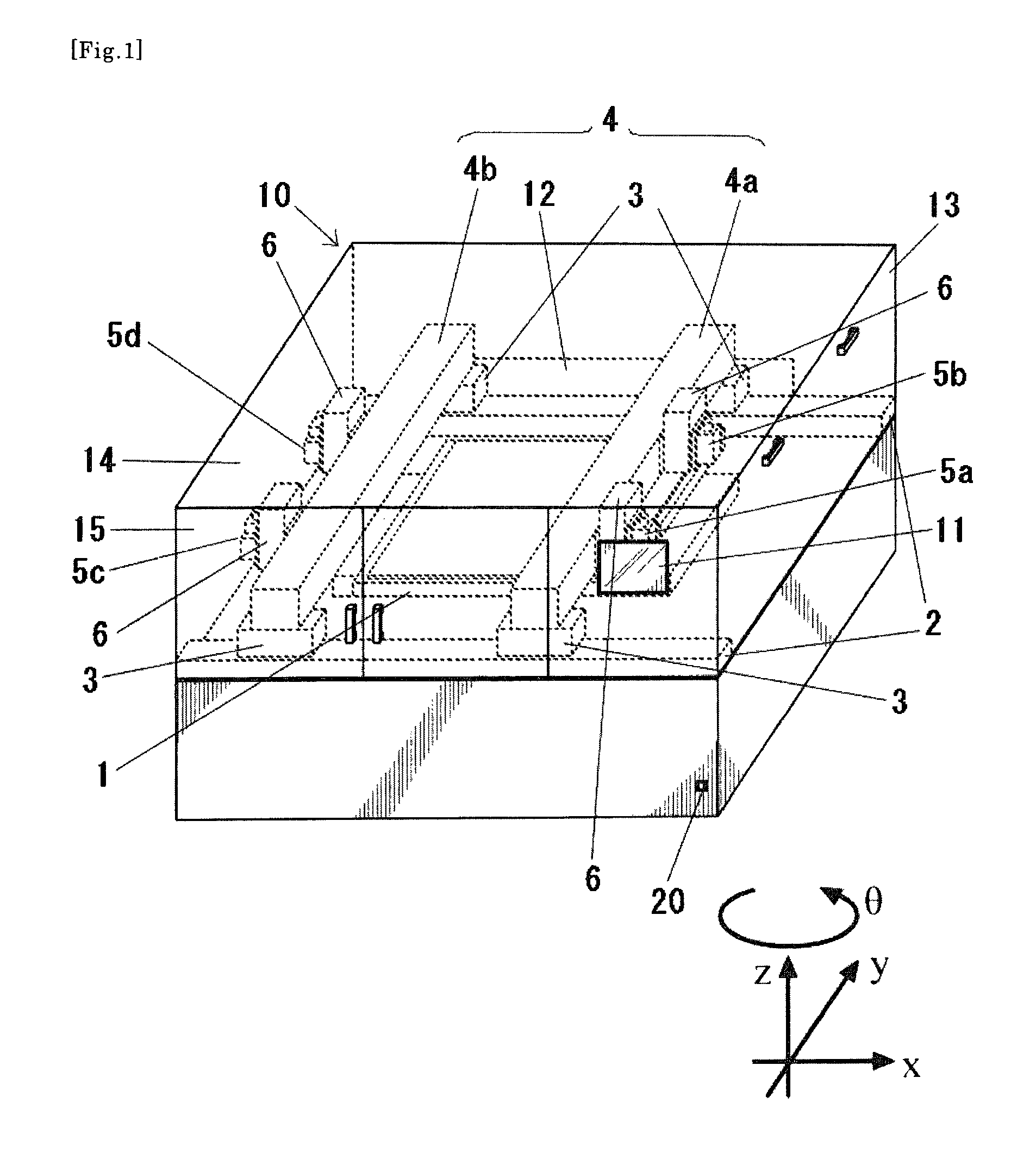
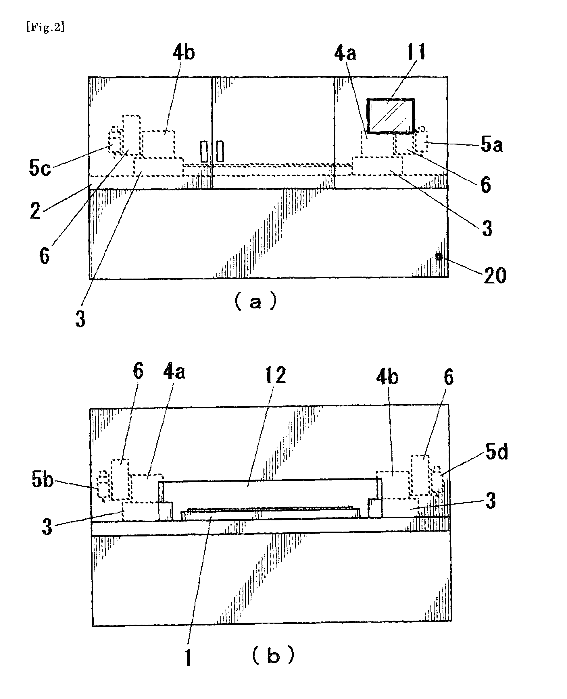
[0059]As shown in FIGS. 1-3, a liquid material application device of this embodiment includes, within a square box 10, a table 1 on which a workpiece is placed, a pair of X-axis slide bases 2 installed on both sides of the table 1 and extending parallel to the X-axis direction, and beams 4 (Y-axis slide bases 4a, 4b) supported on X-axis sliders 3 and extending in the Y-direction.

[0060]The table 1 includes θ-rotation means for moving the workpiece in the direction around a θ-axis to be positioned at a predetermined angle. The table 1 may be directly supported by the θ-rotation means disposed under the table 1, or may be mounted on moving means, which is movable in the X- or Y-axis direction, so as to assist a relative moving operation performed by the X- / Y-axis sliders.

[0061]On each of the pair of X-slide bases 2, two X-axis sliders 3 are disposed to be movable in the lengthwise direction of the X-axis slide base 2. Four X-axis sliders 3 support opposite ends of two beams 4 su...

embodiment 2

[0084]In a device of this embodiment, as shown in FIG. 9, one beam 4 is employed and the application heads 5 are disposed on both right and left side surfaces of the beam 4.

[0085]>

[0086]When carrying in the workpiece, the main control unit 21 moves the X-axis sliders 3 to move the beam 4 to the right end or the left end of each X-axis slide base 2 such that the beam 4 does not overlap with the table 1. After the movement of the beam 4 has been completed, the workpiece is carried in through the carrying in / out opening 12 by the workpiece conveying machine 17. After placing the workpiece on the table 1, the main control unit 21 moves the X-axis sliders 3 and the Y-axis sliders 6 to arrange the application heads 5 corresponding to desired positions on the workpiece. Then, each application head 5 is descended by Z-axis moving means provided on the application head 5, thus applying the liquid material to the workpiece. At that time, the applied liquid material can be drawn in a desired s...


PUM


Abstract

A liquid material application device having high space utilization efficiency and having excellent maintainability. In a liquid material application device for applying a liquid material to a desired position on a surface of a workpiece in a box by relatively moving a nozzle for discharging the liquid material and a table on which the workpiece is placed to face the nozzle, the liquid material application device comprises a carrying in / out opening formed in a side surface of the box and allowing the workpiece to be carried in and carried out therethrough, a beam extending toward the carrying in / out opening, an application head movable in the extending direction of the beam, beam moving means for moving the beam above and in parallel to the table, and a control unit for controlling operations of the aforesaid components.

Description

TECHNICAL FIELD[0001]The present invention relates to a device for applying and dripping liquid materials ranging from a low viscosity material, such as water and alcohol, to a fluid with high consistency, such an adhesive and a paste- or a cream-like industrial material, to a desired position on a workpiece in a desired shape.BACKGROUND ART[0002]Recently, with an increase in demands for a larger-sized display, the size of a glass substrate has exceeded 1 m×1 m and the size of an application (coating) apparatus has also increased correspondingly. A liquid material application device mainly used in the past is of the type that a liquid material is applied while a table on which a substrate is placed is moved in the XY-directions to change the relative positional relationship between a nozzle and a table. However, a gate type structure has been more popularly used for the reasons that an increase in weight of the table makes it more difficult to control the table and increases the inf...

Claims


Application Information

Patent Timeline
Patent Type & Authority Patents(United States)
IPC IPC(8): B05B13/02B05B1/28B05B3/00
CPCH01J9/241H01L51/0004H01L51/56B05C5/0216B05C13/02H10K71/13H10K71/00B05C5/00
Inventor IKUSHIMA, KAZUMASA
Owner MUSASHI ENG INC
Why Eureka
Try Eureka