Eureka AIR delivers breakthrough ideas for toughest innovation challenges, trusted by R&D personnel around the world.

Multiple pulse width modulation

a technology of multi-pulse width and modulation, applied in pulse generators, pulse manipulation, pulse techniques, etc., can solve the problem of high electronic costs

Active Publication Date: 2012-05-15
IMMERSION CORPORATION
View PDF4 Cites 45 Cited by
  • Summary
  • Abstract
  • Description
  • Claims
  • Application Information

AI Technical Summary

Problems solved by technology

Although not an optimal implementation, the low frequency is able to generate a wide range of magnitudes that for haptic effects are sufficient to create compelling vibration effects.
However, because of the complexity of the required driving electronic circuits for A / D or PWM ports, the large amount of required circuit board space, and the high electronic costs, a need developed for a new method and interface for controlling the magnitude of the actuator.

Method used


Image

  • Multiple pulse width modulation
  • Multiple pulse width modulation
  • Multiple pulse width modulation

Examples


Embodiment Construction

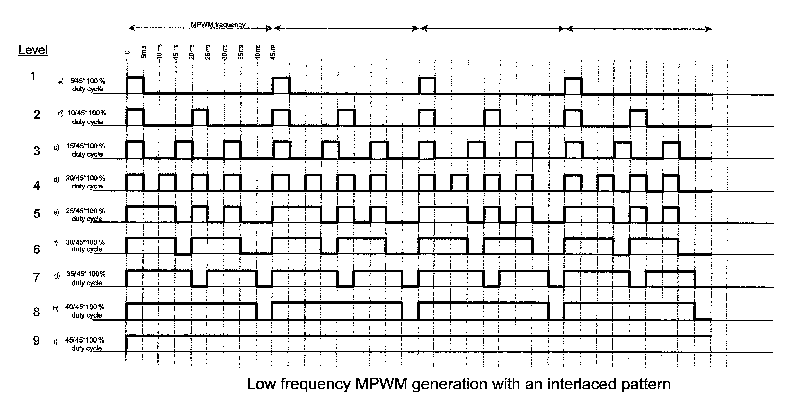
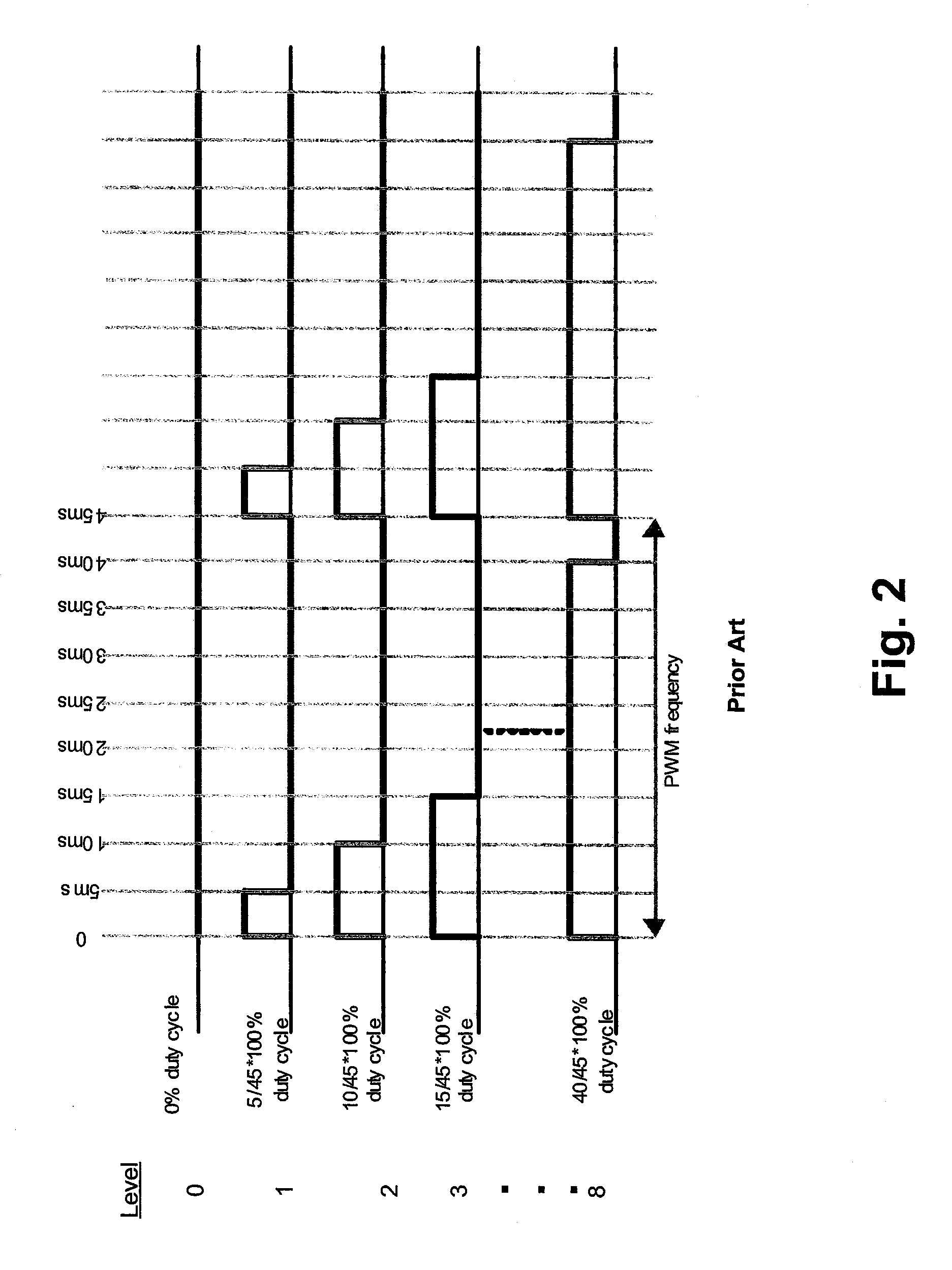
[0011]One embodiment is a controller that generates a multiple pulse width modulation (“MPWM”) signal in which each duty cycle includes a series of pulses instead of a single continuous pulse. The MPWM signal produces the same number of magnitude levels as the prior art PWM signals, but with a higher frequency content. In another embodiment, the number of magnitude levels is increased.

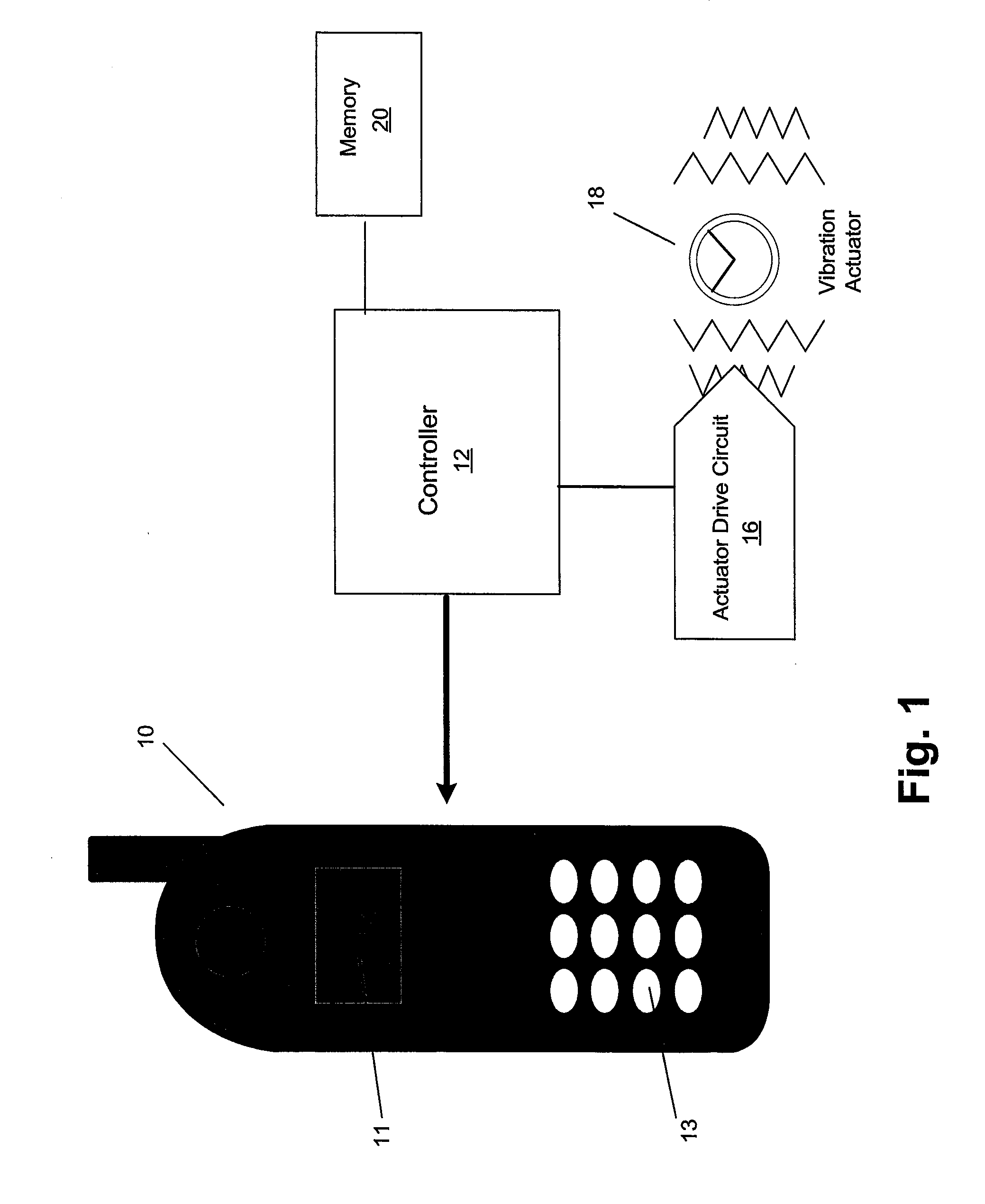
[0012]FIG. 1 is a block diagram of a cellular telephone 10 in accordance with one embodiment. Telephone 10 includes a screen 11 and keys 13. In one embodiment, keys 13 are mechanical type keys. In another embodiment, keys 13 can be implemented by a touchscreen so that keys 13 are touchscreen keys, or can be implemented using any method. Internal to telephone 10 is a haptic feedback system that generates vibrations on telephone 10. In one embodiment, the vibrations are generated on the entire telephone 10. In other embodiments, specific portions of telephone 10 can be haptically enabled by the haptic fe...


PUM


Abstract

A method of generating a MPWM signal for a portable device such as a cellular telephone. For a first duty cycle that includes a MPWM frequency having N magnitude levels, the method generates a first waveform comprising a first and a second On pulse during a first MPWM frequency period. The first and second On pulses are separated by an Off period.

Description

FIELD OF THE INVENTION[0001]One embodiment is directed to generating a control signal. More particularly, one embodiment is directed to generating a control signal having multiple pulse width modulation.BACKGROUND INFORMATION[0002]Electronic device manufacturers strive to produce a rich interface for users. Conventional devices use visual and auditory cues to provide feedback to a user. In some interface devices, kinesthetic feedback (such as active and resistive force feedback) and / or tactile feedback (such as vibration, texture, and heat) is also provided to the user, more generally known collectively as “haptic feedback.” Haptic feedback can provide cues that enhance and simplify the user interface. Specifically, vibration effects, or vibrotactile haptic effects, may be useful in providing cues to users of electronic devices to alert the user to specific events, or provide realistic feedback to create greater sensory immersion within a simulated or virtual environment.[0003]Hapti...

Claims


Application Information

Patent Timeline
Patent Type & Authority Patents(United States)
IPC IPC(8): H03K7/08
CPCH03K3/017
Inventor CRUZ-HERNANDEZ, JUAN MANUELGRANT, DANNY A.
Owner IMMERSION CORPORATION
Why Eureka
Eureka Blog
Learn More