
Method and apparatus for spectral-beam combining of fanned-in laser beams with chromatic-dispersion compensation using a plurality of diffractive gratings

a technology of diffractive gratings and spectral beams, which is applied in the direction of lasers, electromagnetic transmission, transmission, etc., can solve the problems of limiting power-scaling capability and small number of sources that can be combined using this approach, and achieve the effect of improving or superior output beam quality

Active Publication Date: 2012-05-15
LOCKHEED MARTIN CORP
View PDF181 Cites 29 Cited by
  • Summary
  • Abstract
  • Description
  • Claims
  • Application Information

AI Technical Summary

Benefits of technology

[0019]In some embodiments, the invention provides methods and apparatus for spectral-beam combining the optical output from a plurality of high-power fiber lasers in a manner that provides improved or superior output beam quality.
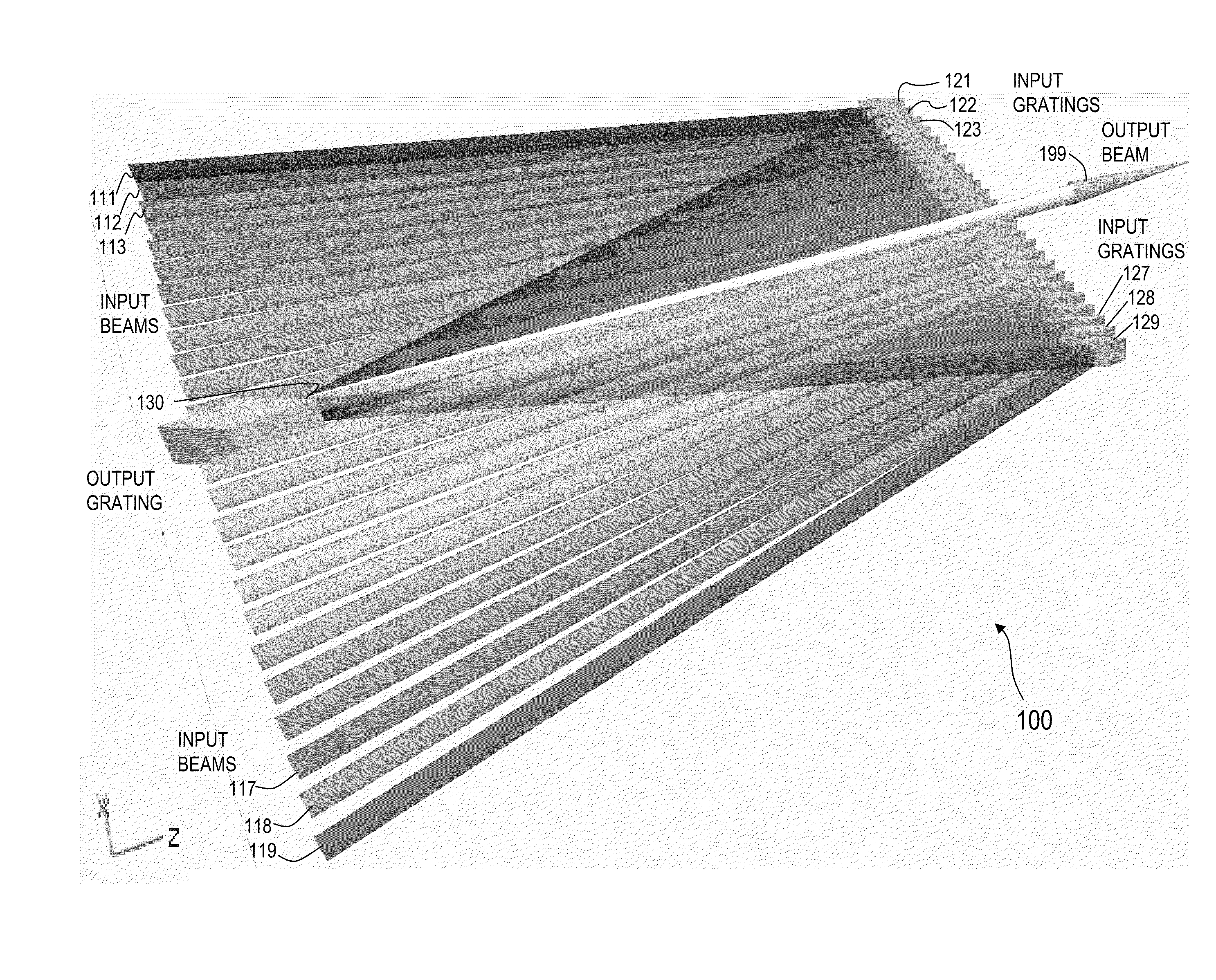
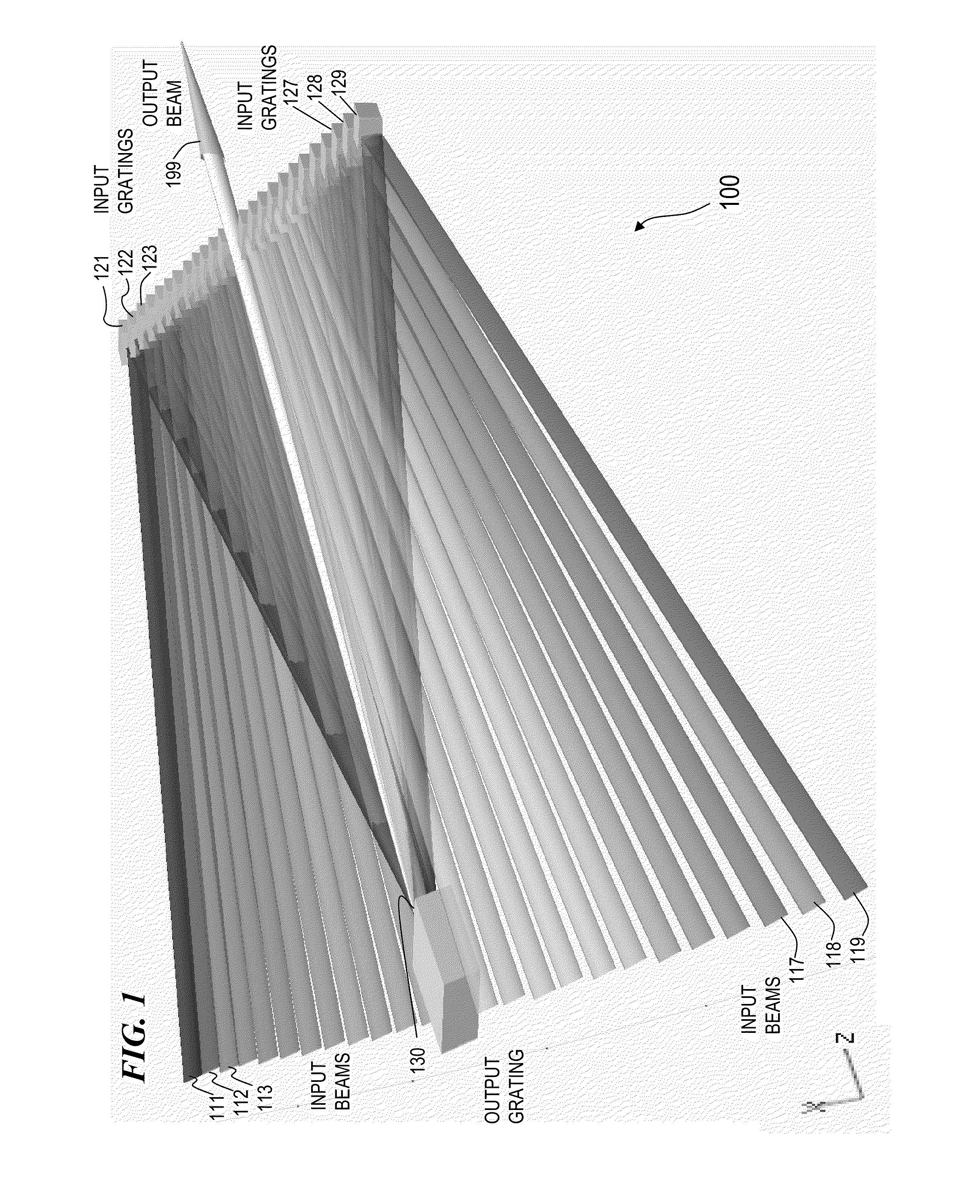
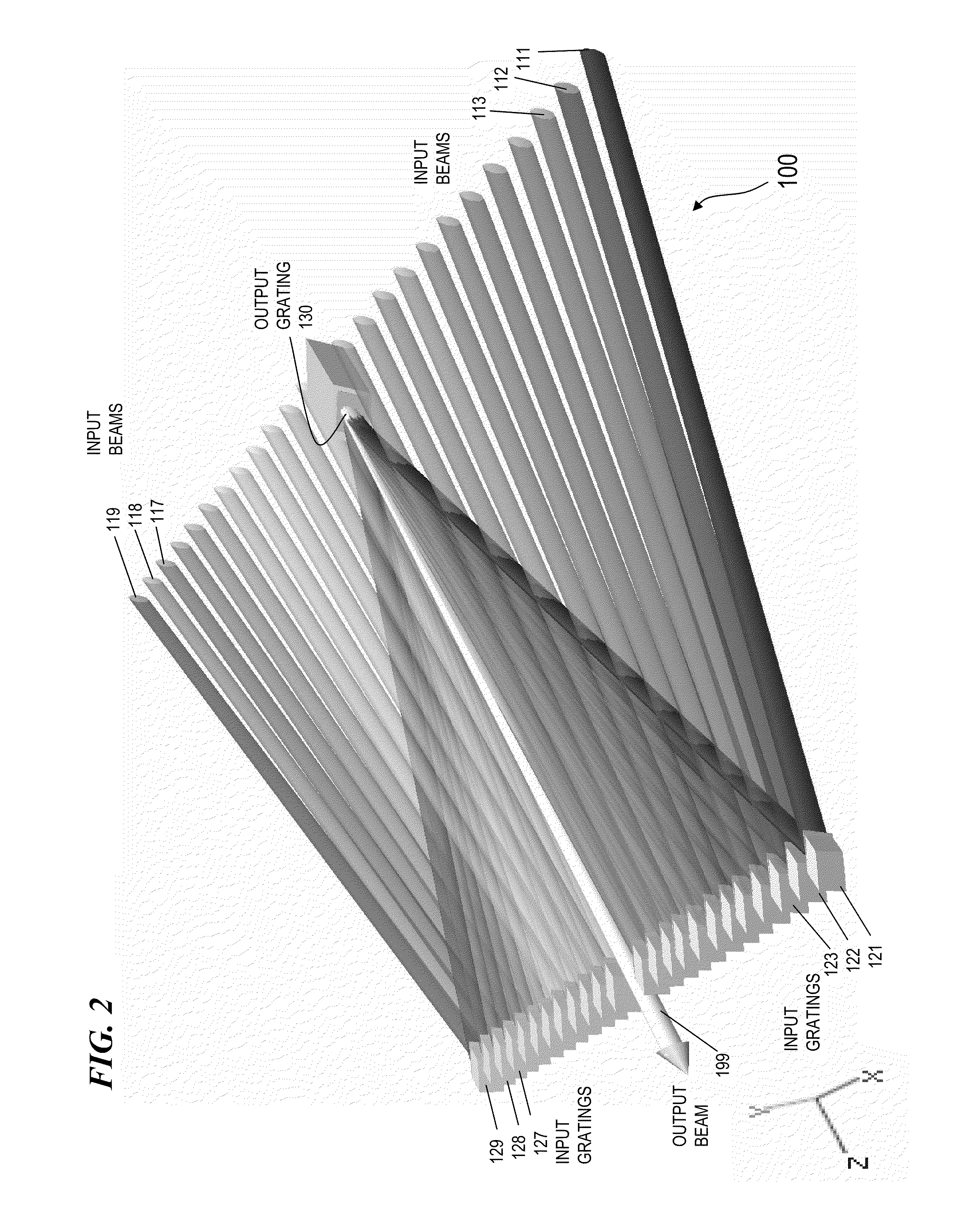
[0020]In some embodiments, the present invention uses two parallel gratings to combine the optical outputs from a plurality of optical fibers, each having a successively higher, slightly different peak wavelength. In some embodiments, the output beams from the plurality of fibers are focused into a row of parallel collimated input beams that impinge on the first grating of the pair and are each diffracted at a plurality of successively higher slightly different angles that all impinge on the second grating of the pair at a common overlapped area, whereupon they all diffract into a single combined output beam having higher power and higher quality (e.g., a small waist and small divergence), as compared to conventional devices.
[0021]One of the main drawbacks of the prior dual-grating SBC concept (as described in U.S. Pat. No. 7,199,924 and U.S. Pat. No. 7,233,442) is that only a small number of sources can be combined using this approach. The minimum beam size for a given power output is determined and limited by the thermally induced aberrations on the second (or output) grating. Increasing the beam size to accommodate additional laser-beam sources quickly leads to large aperture requirements for the first (or input) grating(s) since all the input sources are lined up in a one dimensional (1-D) array. Dead space between sources needed for mounting components and to avoid clipping further limits the power-scaling capability. One objective of some embodiments of the present invention was to find a cavity design that expands space between sources and increases the number of sources that can be combined.

Problems solved by technology

One of the main drawbacks of the prior dual-grating SBC concept (as described in U.S. Pat. No. 7,199,924 and U.S. Pat. No. 7,233,442) is that only a small number of sources can be combined using this approach.
Dead space between sources needed for mounting components and to avoid clipping further limits the power-scaling capability.

Method used


Image

  • Method and apparatus for spectral-beam combining of fanned-in laser beams with chromatic-dispersion compensation using a plurality of diffractive gratings
  • Method and apparatus for spectral-beam combining of fanned-in laser beams with chromatic-dispersion compensation using a plurality of diffractive gratings
  • Method and apparatus for spectral-beam combining of fanned-in laser beams with chromatic-dispersion compensation using a plurality of diffractive gratings

Examples


Embodiment Construction

[0067]Although the following detailed description contains many specifics for the purpose of illustration, a person of ordinary skill in the art will appreciate that many variations and alterations to the following details are within the scope of the invention. Accordingly, the following preferred embodiments of the invention are set forth without any loss of generality to, and without imposing limitations upon the claimed invention.

[0068]In the following detailed description of the preferred embodiments, reference is made to the accompanying drawings that form a part hereof, and in which are shown by way of illustration specific embodiments in which the invention may be practiced. It is understood that other embodiments may be utilized and structural changes may be made without departing from the scope of the present invention.

[0069]The leading digit(s) of reference numbers appearing in the Figures generally corresponds to the Figure number in which that component is first introduc...


PUM


Abstract

Apparatus and method for spectral-beam combining of light from a plurality of high-power lasers (e.g., fiber MOPA lasers) that, in some embodiments, use substantially identical diffraction gratings in a 1-D non-parallel, mutually compensating configuration to combine non-parallel converging input beams in one plane each having a slightly different successively higher wavelength into a single output beam of high quality. In other embodiments, an output grating and one or more input gratings in a 1-D parallel, mutually compensating configuration combine non-parallel input beams in one plane into a single output beam of high quality. In other embodiments, a 2-D plurality of input gratings in a non-parallel configuration combine a plurality of non-parallel input beams not in one plane each having a slightly different successively higher wavelength into a set of converging beams in one plane directed towards an output grating that compensates for chromatic dispersions introduced by the input gratings.

Description

CROSS-REFERENCE TO RELATED APPLICATIONS[0001]This application claims benefit under 35 U.S.C. §119(e) of U.S. Provisional Patent Application No. 60 / 937,770 filed on Jun. 29, 2007, titled “METHOD AND APPARATUS FOR SPECTRAL-BEAM COMBINING OF FANNED-IN LASER BEAMS WITH CHROMATIC-DISPERSION COMPENSATION USING A PLURALITY OF DIFFRACTIVE GRATINGS,” and U.S. Provisional Patent Application No. 60 / 947,398 filed on Jun. 30, 2007, titled “METHOD AND APPARATUS FOR SPECTRAL-BEAM COMBINING OF FANNED-IN LASER BEAMS WITH CHROMATIC-DISPERSION COMPENSATION USING A PLURALITY OF DIFFRACTIVE GRATINGS,” each of which is incorporated herein by reference in its entirety.This application is also related to:U.S. patent application Ser. No. 11 / 751,637 (which issued as U.S. Pat. No. 7,535,631 on May 19, 2009) titled “METHOD AND APPARATUS FOR SPECTRAL-BEAM COMBINING OF FIBER-AMPLIFIED LASER BEAMS USING HIGH-EFFICIENCY DIELECTRIC DIFFRACTIVE GRATINGS”;U.S. Pat. No. 7,391,561 titled “FIBER- OR ROD-BASED OPTICAL SO...

Claims


Application Information

Patent Timeline
Patent Type & Authority Patents(United States)
IPC IPC(8): H01S4/00H04B10/17
CPCH04B10/2513H01S3/005H01S3/2391
Inventor TIDWELL, STEVEN C.LOFTUS, THOMAS H.LEMAIRE, CHARLES A.
Owner LOCKHEED MARTIN CORP
Learn More