Zoom lens and information device

a technology of information device and zoom lens, which is applied in the field of zoom lens, can solve the problems of reducing a total thickness, reducing a size of camera, and a zoom lens having five or more lens groups is not suitable for a small size camera, and achieves the effect of high magnification ratio, less aberration, and high performance photographing function

Active Publication Date: 2012-05-15
RICOH KK
View PDF20 Cites 6 Cited by
  • Summary
  • Abstract
  • Description
  • Claims
  • Application Information

AI Technical Summary

Benefits of technology

[0016]An object of the present invention is to provide a zoom lens capable of achieving a high magnification ratio of 10 times or more and a wide half angle of field of 38 degrees or more as well as less aberration and having a resolving power adapted to an image pickup device having more than 5 to 10 million pixels and also a small size information device having the zoom lens having high performance photographing function.

Problems solved by technology

Although there are various types of the zoom lens for a digital camera, the zoom lens having five or more lens groups is not suitable for a small size camera because it is difficult to reduce a total thickness of the lens groups.
The zoom lens disclosed in Japanese Patent Application Publication No. 2008-107559 has a wide half angle of field of about 40 degrees at the wide angle end but the magnification ratio is only about 5 times. Furthermore, the distortion at the wide angle end is about 10% and therefore even if the distortion is corrected by image processing, an image is degraded due to a large correction amount.
However, the distortion at the wide angle end is about 10% and therefore even if the distortion is corrected by image processing, an image is degraded due to a large correction amount.
That is, the zoom lenses disclosed in both of Japanese Patent Application Publication Nos. 2008-107559 and 2008-112013 are not sufficiently suitable for a zoom lens used as a photographing optical system in a high performance digital camera, or the like.
In Japanese Patent Application Nos. 2005-326743, 2008-076493, 2008-225328 and 2008-146016, the magnification ratio is between about 2.8 times and about 6.8 times and therefore it is not sufficient for satisfying a recently-raised user requirement.
However, the half angle of field is about 31 degrees and therefore user requirement for a wide angle is not sufficiently satisfied.
In Japanese Patent Application No. 2008-026837, the magnification ratio is about 10 times. However, the telephoto ratio is large so that compact size is not sufficiently achieved and aberration correction is required to be improved.
As described above, the configurations disclosed in Japanese Patent Application Publication Nos. 2008-107559 and 2008-112013 do not achieve a zoom lens having a wide angle of field and small size as well as high magnification ratio and less aberration to satisfy the user requirements.

Method used


Image

  • Zoom lens and information device
  • Zoom lens and information device
  • Zoom lens and information device

Examples


first embodiment

[First Embodiment]

[0080]Hereinafter, a zoom lens and an information device according to a first embodiment of the present invention will be explained in detail with reference to accompanying drawings. At first, fundamental embodiments of the present invention will be explained.

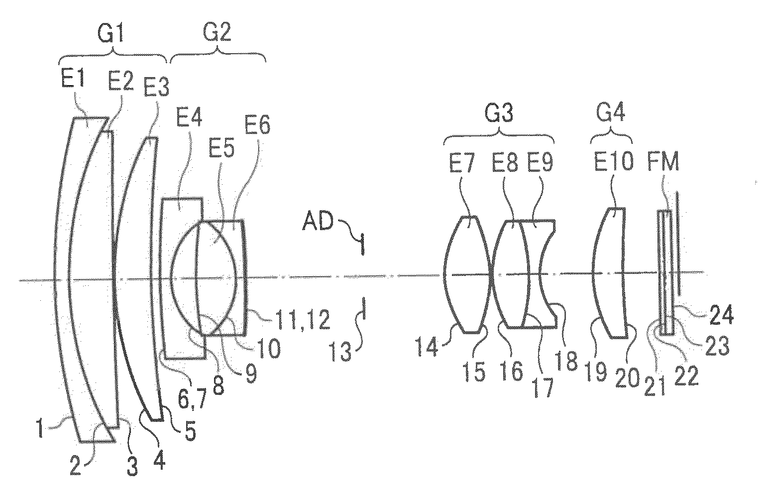
[0081]The zoom lens according to one embodiment of the present invention includes a first lens group having a positive refractive power, a second lens group having a negative refractive power, a third lens group having a positive refractive power, and a fourth lens group having a positive refractive power, which are disposed in order from an object side to an image side, and an aperture stop disposed at an object side of the third lens group. In the zoom lens, in which when changing the magnification of the zoom lens from a wide angle end to a telephoto end, an interval between the first and second lens groups increases, an interval between the second and third lens groups decreases, and an interval between th...

example 5

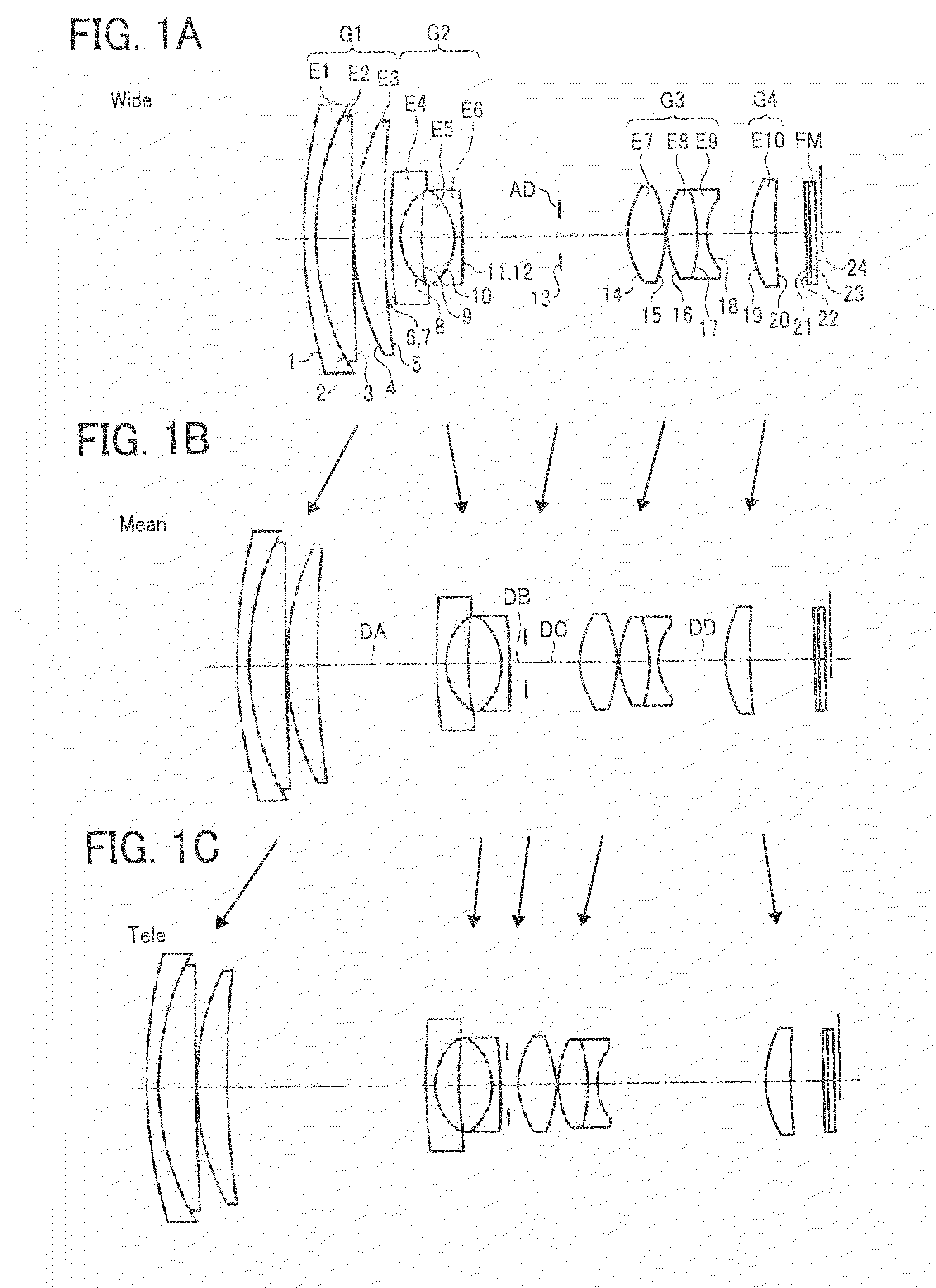
[0196]FIG. 17A to 17C are schematic views of lens configurations of the zoom lens according to the example 5 of the first embodiment of the present invention on a zooming trajectory when zooming from a wide angle end to a telephoto end via a predetermined intermediate focal length position, that is, FIG. 17A is a schematic sectional view of the zoom lens at the wide angle end, FIG. 17B is a schematic sectional view of the zoom lens at the predetermined intermediate focal length position, and FIG. 17C is a schematic sectional view of the zoom lens at the telephoto end. A left side of FIGS. 17A to 17C is an object side of the zoom lens.

[0197]The zoom lens shown in FIG. 17A to 17C includes a first lens group G1 having a positive refracting power, a second lens group G2 having a negative refracting power, a third lens group G3 having a positive refracting power, and a fourth lens group G4 having a positive refracting power, which are disposed in order from an object side along the optic...

example 6

[0215]FIG. 21A to 21C are schematic views of lens configurations of the zoom lens according to the example 6 of the first embodiment of the present invention on a zooming trajectory when zooming from a wide angle end to a telephoto end via a predetermined intermediate focal length position, that is, FIG. 21A is a schematic sectional view of the zoom lens at the wide angle end, FIG. 21B is a schematic sectional view of the zoom lens at the predetermined intermediate focal length position, and FIG. 21C is a schematic sectional view of the zoom lens at the telephoto end. A left side of FIGS. 21A to 21C is an object side of the zoom lens.

[0216]The zoom lens shown in FIG. 21A to 21C includes a first lens group G1 having a positive refracting power, a second lens group G2 having a negative refracting power, a third lens group G3 having a positive refracting power, and a fourth lens group G4 having a positive refracting power, which are disposed in order from an object side along the optic...


PUM


Abstract

A zoom lens includes a first lens group having a positive refractive power, a second lens group having a negative refractive power, a third lens group having a positive refractive power, and a fourth lens group having a positive refractive power, which are disposed in order from an object side, and an aperture stop disposed at an object side of the third lens group. When changing the magnification from a wide angle end to a telephoto end, an interval between the first and second lens groups increases, an interval between the second and third lens groups decreases, and an interval between the third and fourth lens groups increases. The first lens group includes a negative lens, a positive lens, and a positive lens, in order from the object side. Predetermined conditions of a refractive index of the negative lens E1 for a d line, an Abbe number for d line, and a relative partial dispersion are satisfied.

Description

CROSS REFERENCE TO RELATED APPLICATIONS[0001]The present application is based on and claims priority from Japanese Application Numbers, 2009-160297 and 2009-160299 filed on Jul. 6, 2009, and 2009-209864 filed on Sep. 10, 2009, the disclosure of which is hereby incorporated by reference herein in its entirety.BACKGROUND OF THE INVENTION[0002]1. Field of the Invention[0003]The present invention relates to a zoom lens adapted to a digital camera configured to obtain an image data of a subject by use of an image pickup device such as a solid-state image pickup device, or the like, more preferably, a small size zoom lens preferably adapted to a video camera configured to obtain a moving image and a digital still camera configured to photograph a still image and an information device having a photographing function by use of such a zoom lens as a photographing optical system.[0004]2. Description of the Related Art[0005]Recently, instead of a still camera in a film type using a silver salt...

Claims


Application Information

Patent Timeline
Patent Type & Authority Patents(United States)
IPC IPC(8): G02B15/14H04N5/225
CPCG02B13/18G02B15/173G02B15/144113
Inventor TAKANO, YOHEIATSUUMI, HIROMICHI
Owner RICOH KK
Why Eureka
Try Eureka