Windshield wiper device

a wiper and windshield technology, applied in vehicle maintenance, vehicle cleaning, furniture parts, etc., can solve the problems of preventing the axial movement of the wiper shaft during wiper operation, and achieve the effect of simple and therefore cost-effective, high level of time dimensional stability

Inactive Publication Date: 2012-05-22
ROBERT BOSCH GMBH
View PDF13 Cites 23 Cited by
  • Summary
  • Abstract
  • Description
  • Claims
  • Application Information

AI Technical Summary

Benefits of technology

[0003]The objective of the invention is improving a windshield wiper device of the type cited at the outset to the effect that the high requirements for pedestrian impact protection are fulfilled, and, at the same time, trouble-free operation of the windshield wiper device is guaranteed.
[0004]The invention attains the stated objective with a windshield wiper device of the type cited at the outset, in which, in accordance with the invention, the at least one wiper shaft can be displaced under the action of a force. When a pedestrian makes impact with the windshield wiper device the wiper shaft yields to the impact force so that the windshield wiper device does not represent a risk of injury to the pedestrian. As a result, the windshield wiper device fulfills the high requirements for pedestrian impact protection. Because the windshield wiper device dispenses with a predetermined breaking point, trouble-free wiper operation is made possible while simultaneously meeting the requirements for pedestrian impact protection.

Problems solved by technology

As a result, displacement of the wiper shaft in the axial direction during wiper operation is precluded.

Method used


Image

  • Windshield wiper device
  • Windshield wiper device
  • Windshield wiper device

Examples


Embodiment Construction

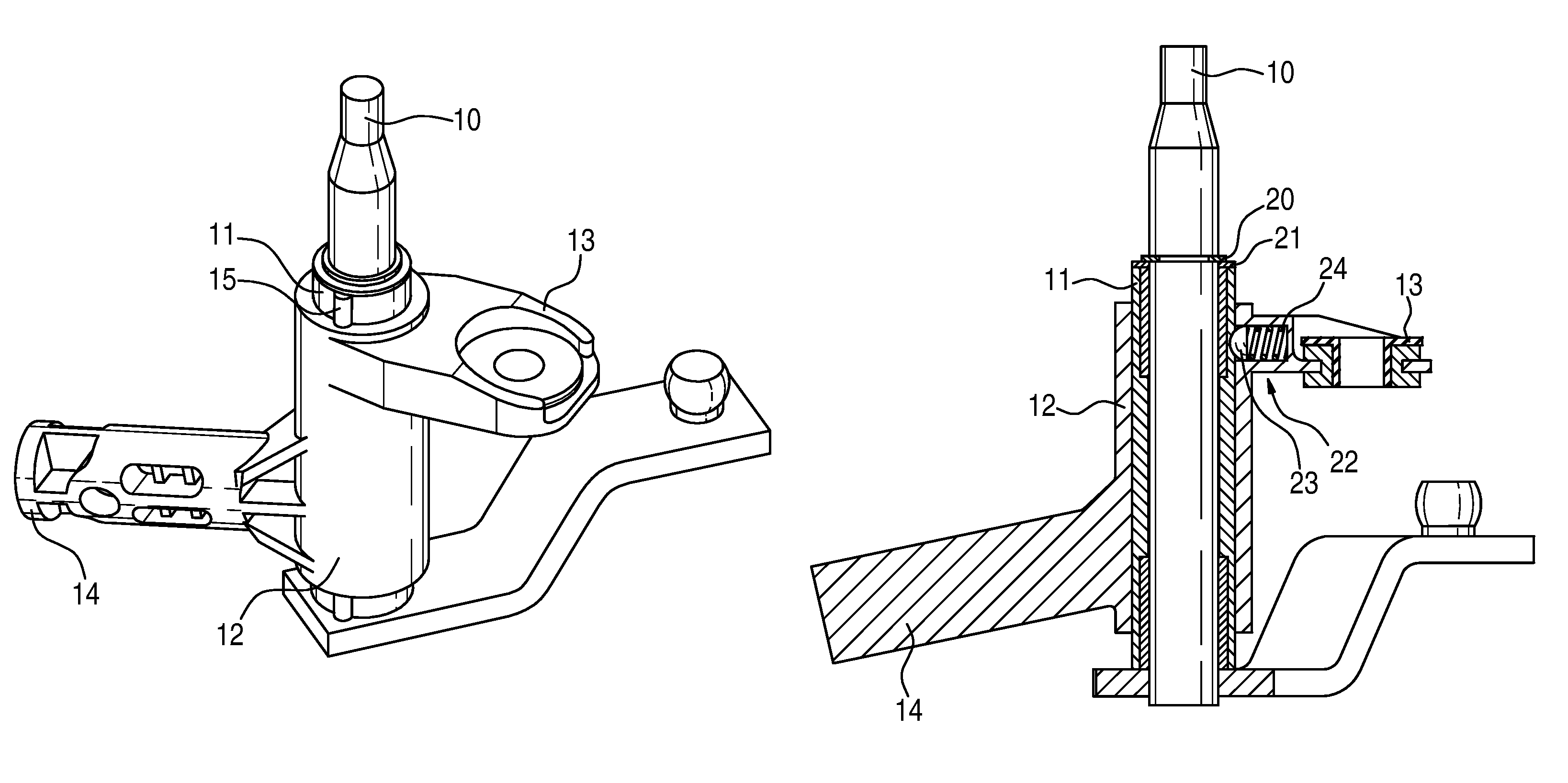
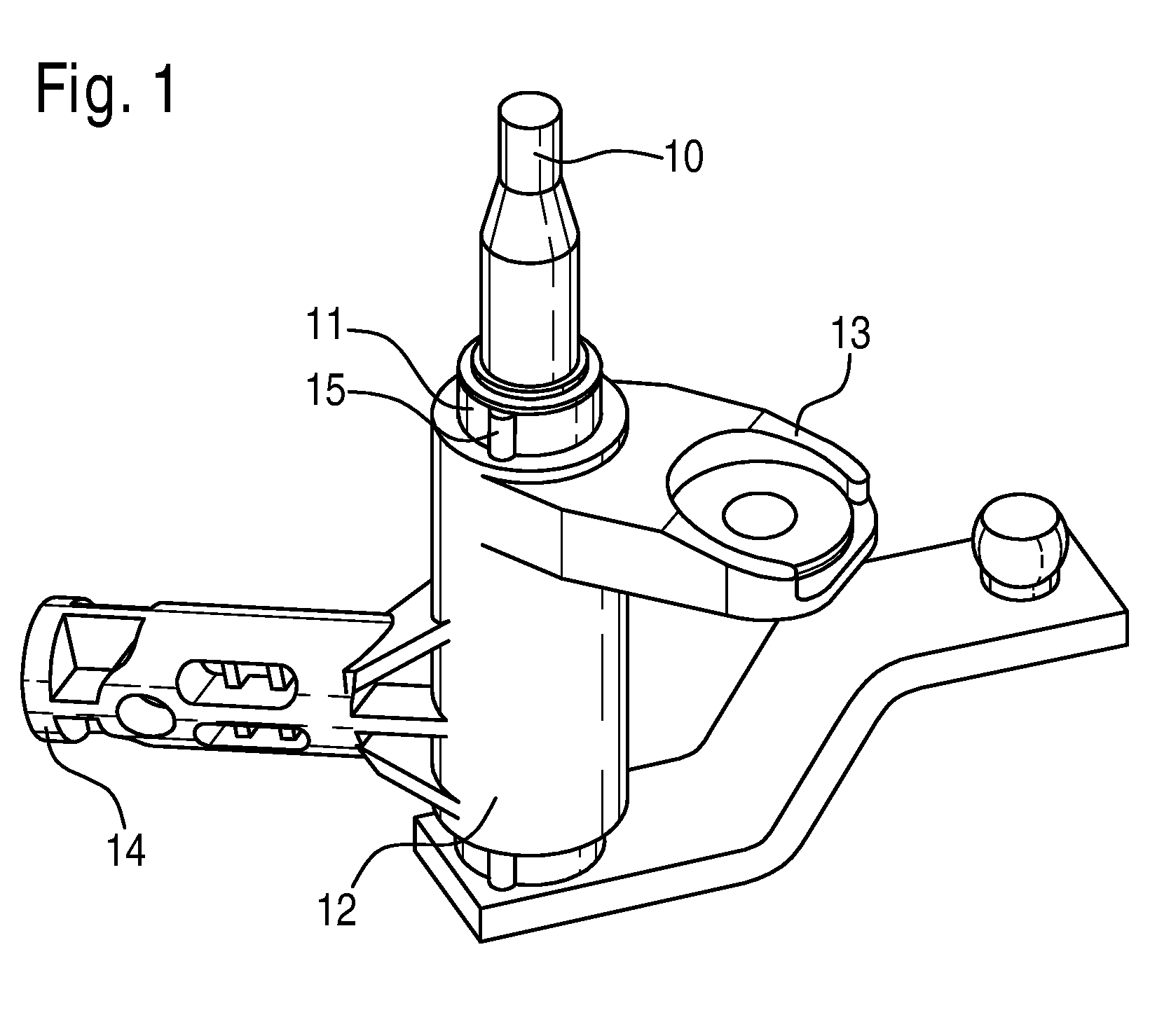
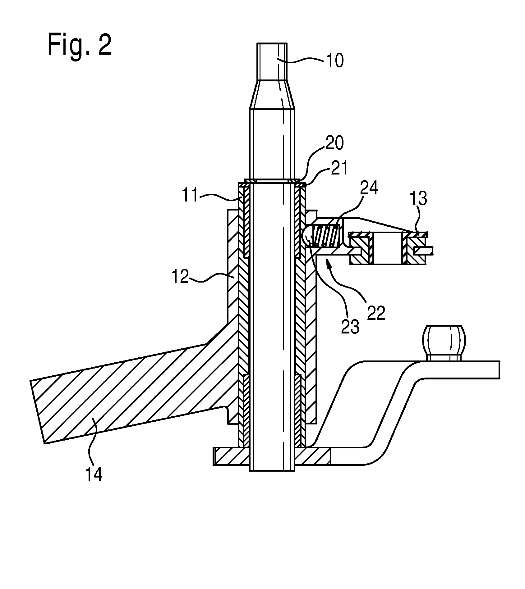
[0025]FIGS. 1 and 2 show a wiper shaft 10, which is inserted into a sleeve 11. The sleeve 11 is inserted into a molded tube 12. Arranged on the molded tube 12 is a holding eye 13, which can be used for mounting the molded tube 12 to a vehicle body (not shown here in greater detail). Moreover, a crimp pin 14 is arranged on the molded tube 12, which can be inserted into a tubular plate (also not shown).

[0026]The sleeve 11 together with the wiper shaft 10 is displaceable in the axial direction relative to the molded tube 12. As a result, the wiper shaft 10 can be displaced downwardly in a pedestrian impact with the wiper shaft 10, thereby reducing the risk of injury to the pedestrian.

[0027]The wiper shaft 10 is connected to the sleeve 11 in the axial direction in a fixed manner by a securing ring 20 and a washer 21 arranged beneath it (see FIG. 2). As a result, the wiper shaft 10 and the sleeve 11 always execute axial displacements jointly.

[0028]The sleeve 11 has a longitudinal wedge 1...


PUM


Abstract

The invention relates to a windshield wiper device, particularly for a motor vehicle, comprising at least one wiper shaft (10). Prior art windshield wiper devices having predetermined breaking points exist in order to meet the high demands of pedestrian impact protection. However, the risk of these predetermined breaking points rupturing during the operation of the wiper exists in this type of windshield wiper device. In addition it cannot be guaranteed that the predetermined breaking point ruptures in the event of a pedestrian impact. Therefore, in the inventive windshield wiper device, the at least one wiper shaft (10) can be displaced under the action of a force.

Description

BACKGROUND OF THE INVENTION[0001]The invention relates to a windshield wiper device, in particular for a motor vehicle, comprising at least one wiper shaft.[0002]Nowadays, high requirements are being placed on windshield wiper devices with respect to pedestrian impact protection. No parts that represent a risk of injury to the pedestrian may project from the vehicle. For this reason, there are windshield wiper devices with predetermined breaking points so that the windshield wiper device yields from the danger zone in an impact with a pedestrian. The predetermined breaking points are provided in an area of an attachment between a wiper bearing and a vehicle body. The disadvantage of this, however, is that the predetermined breaking points lie in the main load area of the wiper bearing, thereby also stressing the predetermined breaking points during wiper operation. The strength and the rigidity of the predetermined breaking points depend upon the material properties and the manufact...

Claims


Application Information

Patent Timeline
Patent Type & Authority Patents(United States)
IPC IPC(8): B60S1/04B60S1/16B60S1/06
CPCB60S1/0488B60S1/3493Y10S403/03
Inventor BOOS, TINO
Owner ROBERT BOSCH GMBH
Why Eureka
Try Eureka