Self-retracting lifeline systems and braking systems therefor

a lifeline system and self-retracting technology, applied in the field of lifeline systems, can solve the problems of low strength, complex interaction parts, insufficient ruggedness, and sudden lock of the drum assembly, and achieve the effects of less complex, less expensive, and reduced fall distan

Active Publication Date: 2012-05-22
HONEYWELL INT INC
View PDF16 Cites 54 Cited by
  • Summary
  • Abstract
  • Description
  • Claims
  • Application Information

AI Technical Summary

Benefits of technology

[0026]Thus, in several embodiments, the present invention provides acceleration-actuated stop, brake or catch devices, systems or methods for self retracting lifeline systems used for personal fall protection. Self-retracting lifeline systems of the present invention allow a user to move about freely by releasing or retracting a lifeline as needed. However, if the user were to fall, the stop, brake or catch devices or systems of the present invention lock the drum assembly of the self-retracting lifeline to reduce the fall distance. The braking devices, systems and / or methods of the present invention are significantly less complex, less costly and more rugged than brake mechanisms found on currently available self-retracting lifeline systems.

Problems solved by technology

For example, when the safety line (for example, rope, cable or web) being pulled from the self-retracting lifeline system causes the drum assembly to rotate above a certain angular velocity, a brake mechanism can cause the drum assembly to suddenly lock.
Currently available acceleration braking systems typically include a system of low strength, complexly interacting parts and have not been widely accepted in the fall protection arts.
Although a number of braking mechanisms have been developed for use in connection with self-retracting lifeline and other systems, such mechanisms are often complex (for example, requiring a significant number of interconnected and often complexly operating components), relatively high in cost and insufficiently rugged.

Method used


Image

  • Self-retracting lifeline systems and braking systems therefor
  • Self-retracting lifeline systems and braking systems therefor
  • Self-retracting lifeline systems and braking systems therefor

Examples


Embodiment Construction

[0044]As used herein and in the appended claims, the singular forms “a,”“an”, and “the” include plural references unless the content clearly dictates otherwise. Thus, for example, reference to “a connector” includes a plurality of such connectors and equivalents thereof known to those skilled in the art, and so forth, and reference to “the connector” is a reference to one or more such connectors and equivalents thereof known to those skilled in the art, and so forth.

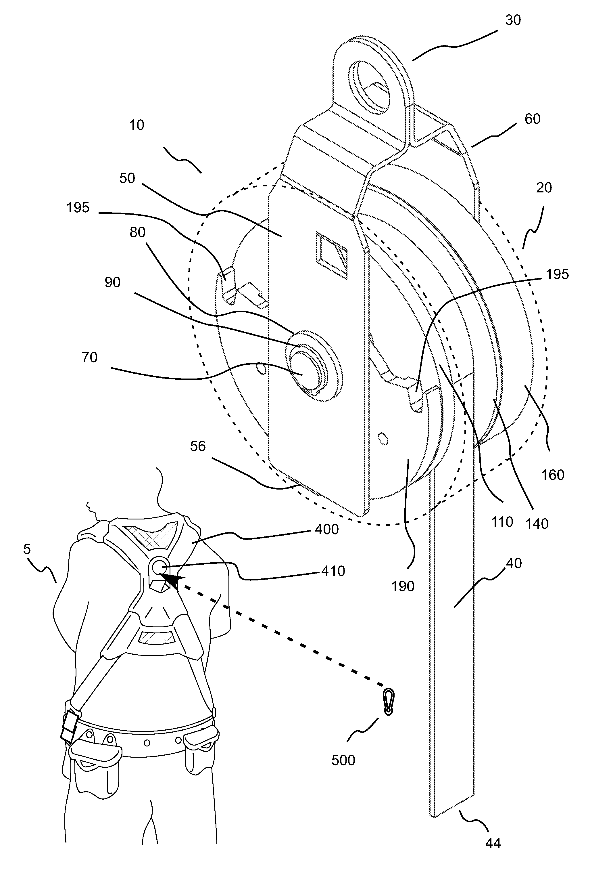
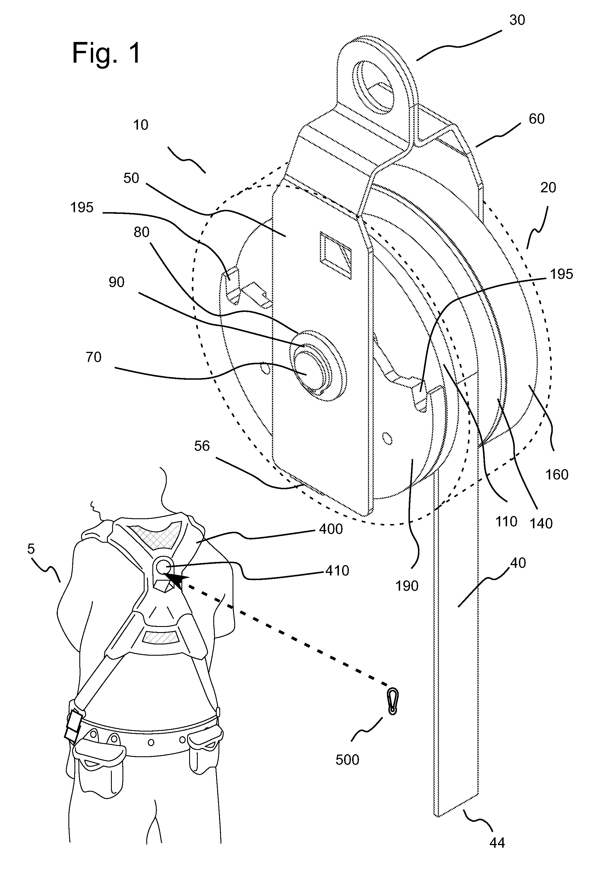
[0045]FIG. 1 illustrates one embodiment of a self-retracting lifeline system 10 of the present invention wherein an outside cover or housing 20 is shown schematically in dashed lines. Cover 20 (which can, for example, be formed in two halves or housing members as known in the art) serves to protect internal mechanisms of self-retracting lifeline from damage, but otherwise does not significantly affect the operation of such internal mechanisms. In normal use, self-retracting lifeline 10 can, for example, be connected via ...


PUM


Abstract

A lifeline system includes a lifeline and a drum assembly around which the lifeline is coiled. The drum assembly is rotatable about a first axis in a first direction during extension of the lifeline and in a second direction, opposite of the first direction, during retraction of the lifeline. The lifeline system further includes a tensioning mechanism in operative connection with the drum assembly to impart a biasing force on the drum assembly to bias the drum assembly to rotate about the first axis in the second direction. The lifeline system further comprises a braking mechanism in operative connection with the drum assembly. The braking mechanism includes a catch that is rotatable relative to the drum assembly about a second axis that is not concentric with the first axis. The second axis is operatively connected to the first axis so that the second axis rotates about the first axis in the same direction as the drum assembly when the drum assembly is rotating about the first axis. A center of mass of the catch is located in the vicinity of the second axis. The catch rotates about the second axis in the second direction when the drum assembly is rotated in the first direction at at least a determined angular acceleration to cause an abutment section of the catch to abut an abutment member of the lifeline system (for example, by moving radially outward a sufficient amount) and stop the rotation of the drum assembly.

Description

CROSS-REFERENCE TO RELATED APPLICATION[0001]This application claims benefit of U.S. Provisional Patent Application Ser. No. 61 / 031,336, filed Feb. 25, 2008, and U.S. Provisional Patent Application Ser. No. 61 / 045,808, filed Apr. 17, 2008, the disclosures of which are incorporated herein by reference.BACKGROUND OF THE INVENTION[0002]The present invention relates to lifeline systems and, particularly, to self-retracting lifeline systems and braking systems therefore.[0003]The following information is provided to assist the reader to understand the invention disclosed below and the environment in which it will typically be used. The terms used herein are not intended to be limited to any particular narrow interpretation unless clearly stated otherwise in this document. References set forth herein may facilitate understanding of the present invention or the background of the present invention. The disclosures of all references cited herein are incorporated by reference.[0004]Many device...

Claims


Application Information

Patent Timeline
Patent Type & Authority Patents(United States)
IPC IPC(8): A62B1/08
CPCA62B1/10
Inventor PARKER, THOMAS W.BALQUIST, ROSS
Owner HONEYWELL INT INC
Why Eureka
Try Eureka