
Cockpit cross member for a motor vehicle

a cross member and motor vehicle technology, applied in the direction of superstructure subunits, monocoque constructions, understructures, etc., can solve the problems of uncontrollable brittle fracture and buckling in the event of a crash, undesirable heavy steel basic member, and low modulus of elasticity of light metal, so as to reduce the transmission of such torsional vibrations to the cockpit cross member, the effect of low deformation and easy formation

Active Publication Date: 2012-05-22
DR ING H C F PORSCHE AG
View PDF49 Cites 6 Cited by
  • Summary
  • Abstract
  • Description
  • Claims
  • Application Information

AI Technical Summary

Benefits of technology

[0009]The invention was made in view of the findings noted above, and is directed to a cockpit cross member with a basic member being designed as a light-metal cast structure, to at least partially “absorb” the forces occurring in the event of the motor vehicle crashing, and particularly in the event of a side crash in the region of a left or right fastening bracket. For this purpose, an adjusting element is located in the force path in front of the basic member for protection in the event of a crash. The adjusting element here is intended to refer to a component that dissipates a considerable part of the force exerted in the event of the motor vehicle crashing by energy absorption by means of an elastic, plastic and / or collapsing deformation. The arrangement of the adjusting element in the force path in front of the basic member assures that the adjusting element is acted upon first by means of the fastening bracket with the forces that occur in the event of a crash. Therefore, in the event of a crash, a defined force is dissipated reliably and therefore the light-metal cast structure is protected securely against brittle fracture and / or buckling. Thus, the cockpit cross member is particularly light and at the same time reliably ensures the protection of the vehicle occupants in the event of a crash. Additionally or alternatively such an adjusting element may be arranged in front of the basic member in the longitudinal direction of the motor vehicle for at least partially absorbing the forces occurring in the region of a front fastening bracket in the event of a head-on crash.
[0012]The adjusting element preferably is designed to absorb only some of the forces exerted on the cockpit cross member in the event of a crash. For example, the adjusting element may absorb precisely that part of the force exerted on the cockpit cross member that cannot be absorbed by the basic member without breaking or buckling. Put another way, the forces occurring in the event of a crash are divided modularly between the basic member, which is loaded, for example, up to its fracture limit, and the adjusting element which is located in front of the basic member in the direction of force and absorbs the rest of the forces. This enables the adjusting element to be dimensioned in a manner suitable for requirements by the low deformability of the basic member designed as a light-metal cast structure being taken into consideration.
[0013]A vibration-optimized cockpit cross member can be achieved if a lateral fastening bracket is connected to the vehicle body in a lower region of an A pillar of the motor vehicle, for example in the vicinity of the vehicle floor. This vibration-optimization of the cockpit cross member is achieved because, in this region, torsional vibrations, in particular, have only a relatively low amplitude, and therefore the transmission of such torsional vibrations to the cockpit cross member can be reduced significantly.
[0014]The adjusting element preferably is surrounded at least partially by the basic member to provide a particularly compact cockpit cross member. For example, the light-metal cast construction of the basic member enables the basic member to be formed easily with an opening for receiving the adjusting element.

Problems solved by technology

However, a steel basic member is undesirably heavy.
However, light metal is more brittle than steel and has a low modulus of elasticity.
However, such an uncontrolled brittle fracture and buckling in the event of a crash are undesirable.

Method used


Image

  • Cockpit cross member for a motor vehicle
  • Cockpit cross member for a motor vehicle

Examples


Embodiment Construction

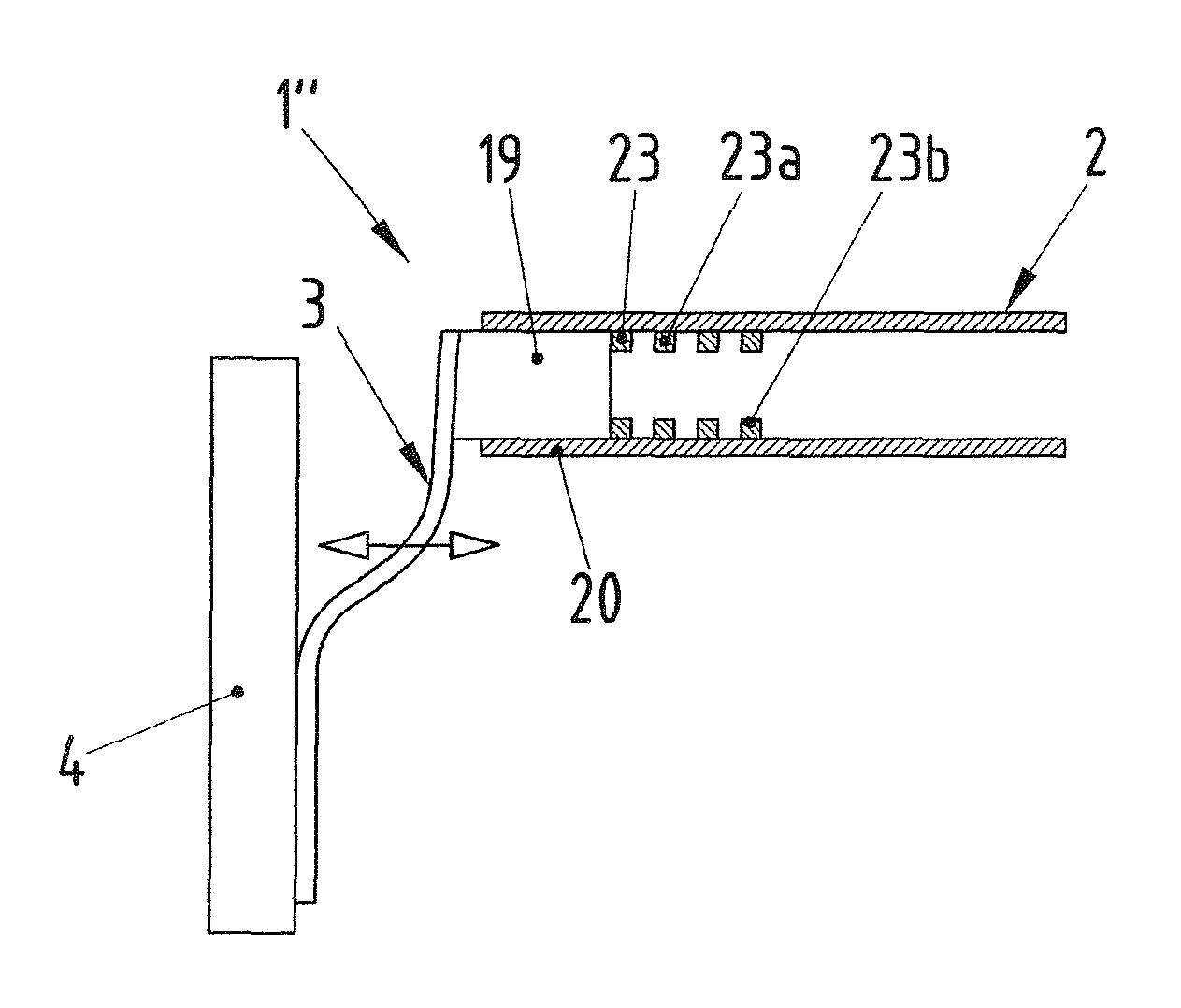
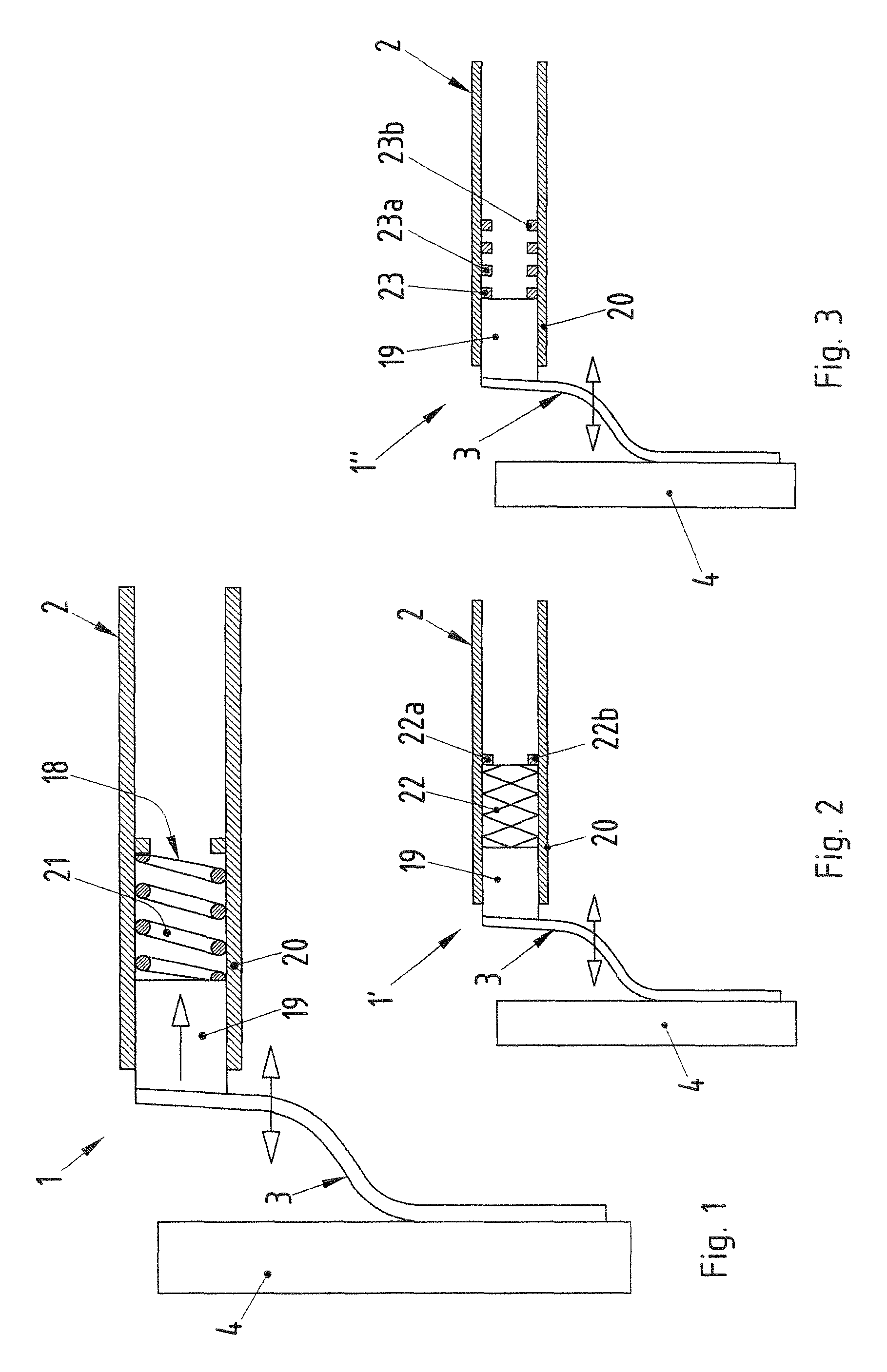
[0021]Cockpit cross members in accordance with the invention are illustrated in FIGS. 1 to 3 and are identified respectively by the reference numerals 1, 1′ and 1″. Each of the cockpit cross members 1, 1′ and 1″ has a basic member 2 that extends over substantially the vehicle width in the transverse direction of the vehicle, and left and right lateral fastening brackets 3. Only a left fastening bracket 3 is illustrated in each of FIGS. 1 to 3 for simplification. The lateral fastening bracket 3 is provided for connecting the cockpit cross member 1, 1′, 1″ to a vehicle body in the lower region of the A pillar 4. The lateral fastening bracket 3 is designed, for example, as an extruded profile made from light metal, such as aluminum. As an alternative, the lateral fastening bracket 3 is configured as a leaf spring that is flexible in a spring-elastic manner in the transverse direction of the vehicle. The lateral fastening bracket 3 therefore defines a first adjusting element that provid...


PUM


Abstract

A cockpit cross member (1,1′,1″) for a motor vehicle, has a basic member (2) and at least one fastening bracket (3) for connecting the cockpit cross member to the vehicle body (4). The basic member (2) is designed as a light-metal cast structure, and an adjusting element (18, 19, 20, 21, 22, 23) is provided between the basic member (2) and the fastening bracket (3) to at least partially absorb the force exerted on the cockpit cross member in the event of the motor vehicle crashing.

Description

CROSS-REFERENCE TO RELATED APPLICATIONS[0001]This application claims priority under 35 USC 119 to German Patent Application No. 10 2008 052 007.1 filed on Oct. 10, 2008, the entire disclosure of which is incorporated herein by reference.BACKGROUND OF THE INVENTION[0002]1. Field of the Invention[0003]The invention relates to a cockpit cross member for a motor vehicle.[0004]2. Description of the Related Art[0005]DE 199 26 636 A1 is assigned to the assignee of the subject invention and relates to a cockpit cross member for a motor vehicle. The cockpit cross member has a tubular basic member onto which two lateral fastening brackets can be pushed and fixed. The fastening brackets virtually completely surround some regions of the basic member and are connectable to the motor vehicle body by a fastening plate.[0006]DE 10 2008 006 608 also is assigned to the assignee of the subject invention and discloses another cockpit cross member. DE 10 2008 006 608 was first published after the above-...

Claims


Application Information

Patent Timeline
Patent Type & Authority Patents(United States)
IPC IPC(8): B60J7/00
CPCB62D21/157B62D25/145
Inventor JUNGERT, DIETERMULLER, JOACHIM
Owner DR ING H C F PORSCHE AG
Learn More