Carbon monoxide treatment apparatus for fuel cell

a fuel cell and carbon monoxide technology, applied in the direction of combustible gas catalytic treatment, separation processes, electrochemical generators, etc., can solve the problems of inability to continuously activate catalysts, inability to easily generate catalysts, and inability to treat carbon monoxide and oxidants, so as to promote preferential oxidation reaction, reduce or minimize moisture absorption, and simple structure

Inactive Publication Date: 2012-05-22
SAMSUNG SDI CO LTD
View PDF13 Cites 1 Cited by
  • Summary
  • Abstract
  • Description
  • Claims
  • Application Information

AI Technical Summary

Benefits of technology

[0015]An aspect of an embodiment of the present invention is directed to a carbon monoxide treatment apparatus for a fuel cell that is capable of reducing a concentration level of carbon monoxide by utilizing a preferential oxidation reaction of the carbon monoxide.
[0016]An aspect of an embodiment of the present invention is directed to a carbon monoxide treatment apparatus for a fuel cell that utilizes a simple structure to reduce or minimize absorption of moisture of partially condensed reformed gas into a catalyst.
[0017]An exemplary carbon monoxide treatment apparatus for a fuel cell according to one embodiment of the present invention reduces a concentration level of carbon monoxide included in reformed gas by utilizing a preferential oxidant reaction of the carbon monoxide. The carbon monoxide treatment apparatus for a fuel cell includes a catalyst reaction unit, a channel unit, and a condensate water storage unit. The catalyst reaction unit includes catalysts for promoting the preferential oxidation reaction. The channel unit introduces the reformed gas into the catalyst reaction unit. The condensate water storage unit stores moisture of the reformed gas that has been partially condensed while passing through the channel unit.

Problems solved by technology

Therefore, the conventional carbon monoxide treatment apparatus may interrupt absorption of carbon monoxide and the oxidant gas that participate in the preferential oxidation reaction since the condensate water is absorbed into an activated surface of the catalyst.
Accordingly, the catalyst cannot be continuously activated and heat of reaction for a specific reaction cannot be easily generated so that an initial driving time of the conventional carbon monoxide treatment apparatus is increased, thereby deteriorating performance and efficiency of the carbon monoxide treatment apparatus.

Method used


Image

  • Carbon monoxide treatment apparatus for fuel cell
  • Carbon monoxide treatment apparatus for fuel cell
  • Carbon monoxide treatment apparatus for fuel cell

Examples


Embodiment Construction

[0042]In the following detailed description, only certain exemplary embodiments of the present invention are shown and described, simply by way of illustration. As those skilled in the art would realize, the described exemplary embodiments may be modified in various different ways, all without departing from the spirit or scope of the present invention. Accordingly, the drawings and description are to be regarded as illustrative in nature, and not restrictive.

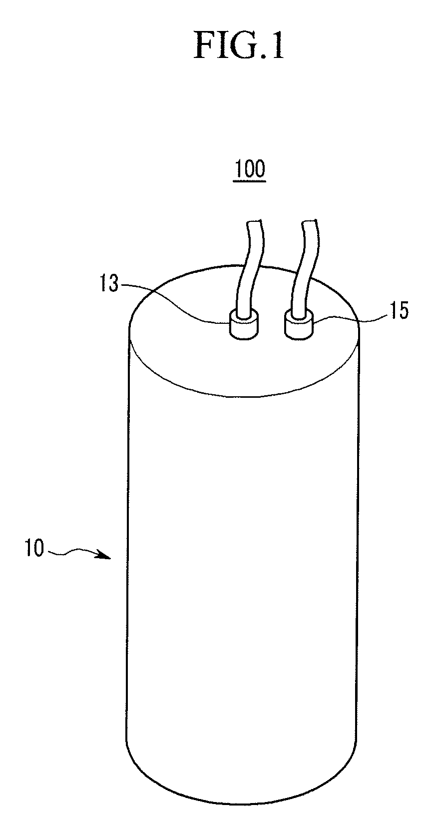
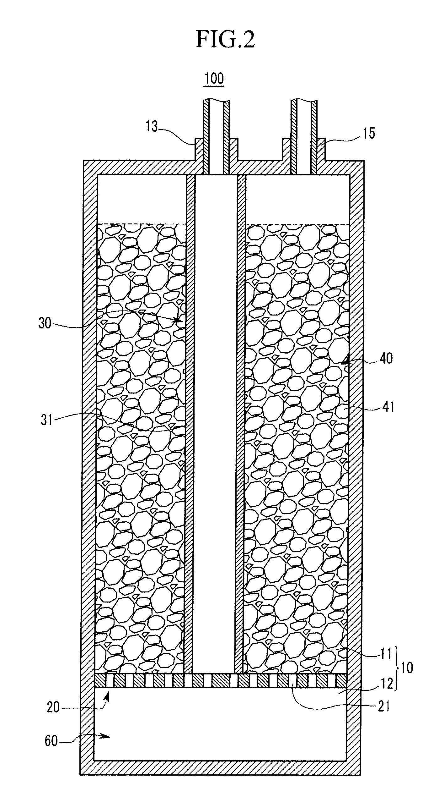
[0043]FIG. 1 is a perspective schematic view of a carbon monoxide treatment apparatus for a fuel cell according to a first exemplary embodiment of the present invention, and FIG. 2 is a cross-sectional schematic view of the treatment apparatus of FIG. 1.

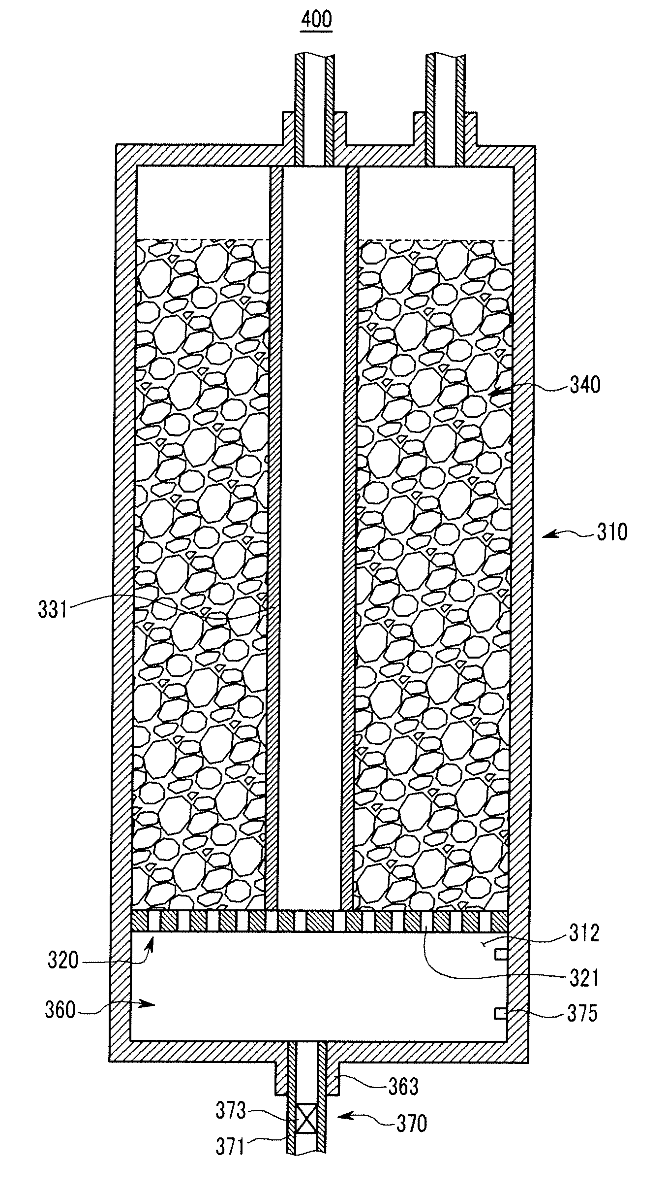
[0044]As shown in FIG. 1 and FIG. 2, a carbon monoxide treatment apparatus 100 is formed of a preferential CO oxidation (PROX) reactor that receives a reformed gas generated by a reformer and an oxidant gas, and reduces a concentration level of carbon monoxide included in the re...


PUM

PropertyMeasurementUnit
concentrationaaaaaaaaaa
electrical energyaaaaaaaaaa
electric energyaaaaaaaaaa

Abstract

A carbon monoxide treatment apparatus according to an exemplary embodiment of the present invention includes: a reactor body; a partitioning plate located inside the reactor body for partitioning an internal space of the reactor body into a first section and a second section; a channel member in the first section for transporting an introduced gas including a reformed gas and an oxidant gas to the second section; and a reaction unit around the channel member of the first section for reducing a concentration level of carbon monoxide in the introduced gas moving through the first section by utilizing a preferential oxidation reaction of the carbon monoxide and the oxidant gas of the introduced gas, wherein moisture of the introduced gas that has been partially condensed when passing through the channel member is stored in the second section.

Description

CROSS-REFERENCE TO RELATED APPLICATION[0001]This application claims priority to and the benefit of Korean Patent Application No. 10-2007-0036454, filed in the Korean Intellectual Property Office on Apr. 13, 2007, the entire content of which is incorporated herein by reference.BACKGROUND OF THE INVENTION[0002]1. Field of the Invention[0003]The present invention relates to a carbon monoxide treatment apparatus. More particularly, the present invention relates to a carbon monoxide treatment apparatus for a fuel cell.[0004]2. Description of the Related Art[0005]A fuel cell is a power generator that generates electrical energy by utilizing a fuel and an oxidant gas.[0006]A fuel cell can be broadly classified into a polymer electrolyte membrane (PEM) fuel cell or a direct oxidation membrane (DOM) fuel cell.[0007]The PEM fuel cell receives a reformed gas generated by a reformer and an oxidant gas, and generates electrical energy by using an electrical-chemical reaction of the reformed gas ...

Claims


Application Information

Patent Timeline
Patent Type & Authority Patents(United States)
IPC IPC(8): B01D53/34
CPCC10K3/04H01M8/0668H01M2008/1095Y02E60/50H01M8/06
Inventor HAN, MAN-SEOKAN, SEONG-JINKIM, JU-YONGLEE, SUNG-CHULLEE, YONG-KULLEE, CHAN-HOKIM, JUN-SIKAHN, JIN-GOO
Owner SAMSUNG SDI CO LTD
Why Eureka
Try Eureka