Method and system for using a MEMS structure as a timing source

a timing source and mems technology, applied in the field of mems devices, can solve the problems of limiting the stability of the frequency and phase noise of the oscillator, and achieve the effect of reducing the additional cos

Active Publication Date: 2012-05-22
INVENSENSE
View PDF12 Cites 7 Cited by
  • Summary
  • Abstract
  • Description
  • Claims
  • Application Information

AI Technical Summary

Benefits of technology

[0007]A method of providing an accurate clock source for electronics that support a MEMS device which has a vibrating MEMS structure is described. The accurate clock is obtained from the oscillating MEMS itself with minimal additional cost. The MEMS oscillation frequency is used as the reference signal for a frequency translator circuit such as PLL, DLL or frequency multiplier which generates the timing source for the supporting electronics.

Problems solved by technology

The quality factor of the filter limits the stability of the frequency and the phase noise of the oscillator.

Method used


Image

  • Method and system for using a MEMS structure as a timing source
  • Method and system for using a MEMS structure as a timing source
  • Method and system for using a MEMS structure as a timing source

Examples


Embodiment Construction

[0017]The present invention relates generally to MEMS devices and more specifically to MEMS devices with a vibrating MEMS element. The following description is presented to enable one of ordinary skill in the art to make and use the invention and is provided in the context of a patent application and its requirements. Various modifications to the preferred embodiments and the generic principles and features described herein will be readily apparent to those skilled in the art. Thus, the present invention is not intended to be limited to the embodiments shown, but is to be accorded the widest scope consistent with the principles and features described herein.

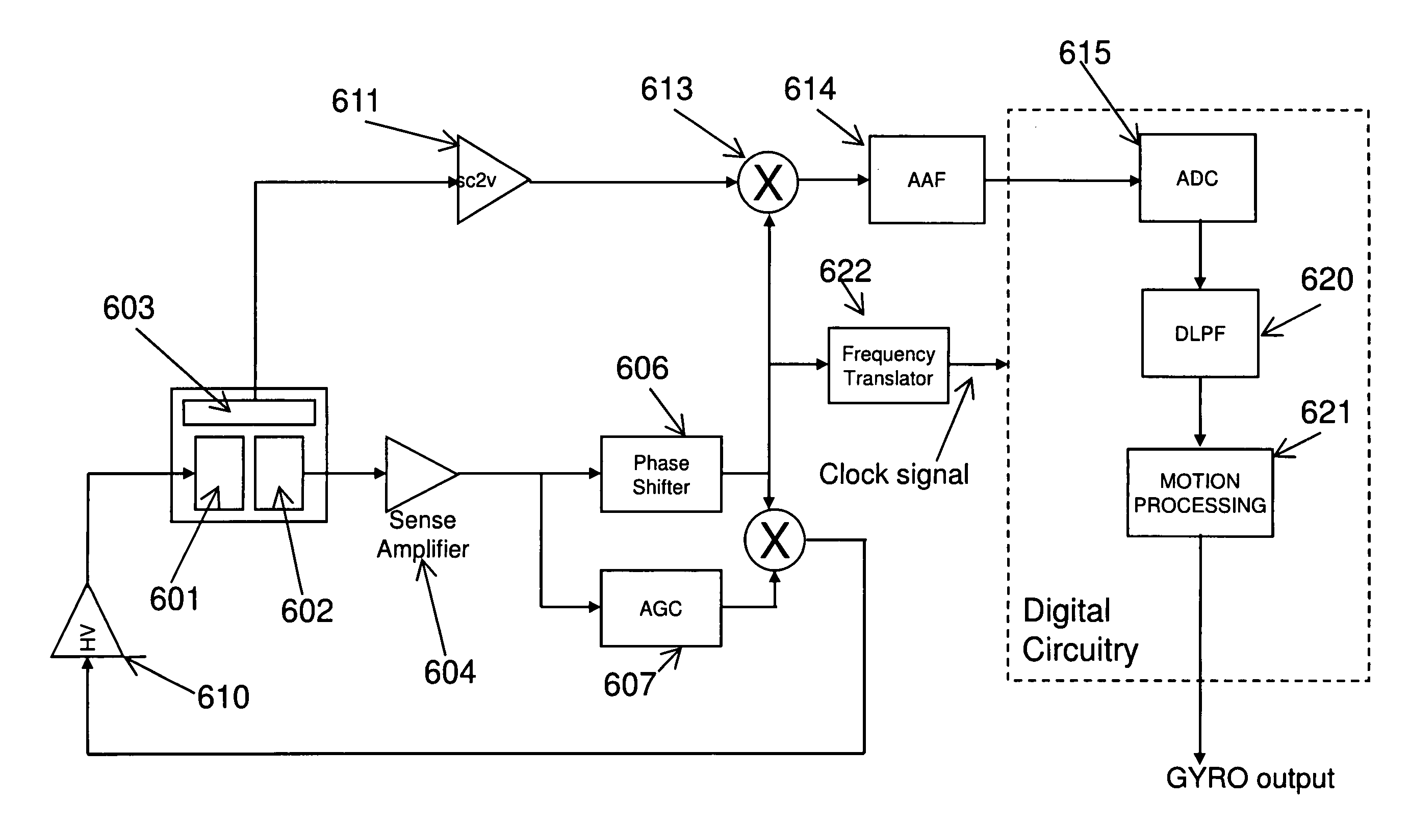
[0018]A variety of MEMS devices uses vibrating micromechanical structures. Vibratory MEMS gyroscopes, resonant accelerometers and scanning MEMS mirrors are some examples of such devices. The resonant structure in these devices provides a high Q as well as the oscillation frequency is very stable over temperature. In general, a ME...


PUM


Abstract

A system and method is disclosed that provides a technique for generating an accurate time base for MEMS sensors and actuators which has a vibrating MEMS structure. The accurate clock is generated from the MEMS oscillations and converted to the usable range by means of a frequency translation circuit.

Description

FIELD OF THE INVENTION[0001]The present invention relates generally to MEMS devices and more specifically to MEMS devices with a vibrating MEMS structure, wherein the primary function of the MEMS structure is not to provide an accurate clock.BACKGROUND OF THE INVENTION[0002]MEMS devices with integrated IC electronics are being used in many consumer applications. For example, MEMS accelerometers are used in air bag deployment, MEMS gyros provide hand jitter information for image stabilization in digital cameras, MEMS microphones are replacing conventional electret microphones in cell phones, vibrating mirrors enable ultra small projectors for consumer applications. In the earlier MEMS devices, the sensor output was usually provided to the outside world by analog signals. In recent years, consumer applications started to require additional features from the MEMS devices. These additional features include providing digital outputs, digital filtering, and interrupt generation upon detec...

Claims


Application Information

Patent Timeline
Patent Type & Authority Patents(United States)
IPC IPC(8): H03B5/30
CPCH03B5/30H03L7/183G01C19/56
Inventor SEEGER, JOSEPHYARALIOGLU, GOKSEN G.CAGDASER, BARIS
Owner INVENSENSE
Why Eureka
Try Eureka