Time-hopping low-power wireless network for turning off and on fluorescent lamps

a low-power wireless network and fluorescent lamp technology, applied in power management, transmission systems, sustainable buildings, etc., can solve the problems of large protocol overhead, large power consumption of the device overall, and substantial disadvantages of some lighting control applications, so as to reduce the persistence of possible collisions and reduce latency.

Active Publication Date: 2012-05-22
IXYS INTL LTD
View PDF9 Cites 6 Cited by
  • Summary
  • Abstract
  • Description
  • Claims
  • Application Information

AI Technical Summary

Benefits of technology

[0005]In each of a plurality of intervals, a starter unit wakes up and listens for a beacon, regardless of whether a beacon is transmitted during that interval or not. The starter unit operates in a low power sleep mode during the majority of the interval. The local master unit can transmit a beacon during the beacon slot time of any interval, but typically only transmits a beacon frequently enough to maintain starter synchronization. If the local master unit wishes to communicate with the starter units with reduced latency, then the local master unit can transmit a beacon in the next interval. Starter units only transmit communications if first commanded to by a beacon. The beacon slot time is varied within the interval (for example, from interval to interval or from group of intervals to group of intervals) in a pseudo-random time-hopping fashion known both to the starter units and to the local master unit. This time-hopping reduces the persistence of possible collisions with similar networks.

Problems solved by technology

Because the relative amount of time the coordinator and the endpoints are active and communicating is much smaller than the amount of time the coordinator and endpoints are in their sleep modes, overall power consumption of the devices is small.
Although such a ZigBee-based lighting control system has many advantages, it has substantial disadvantages in some lighting control applications.
These disadvantages include a large amount of protocol overhead, a high implementation cost, and quite surprisingly a high attendant power consumption.
This time-hopping reduces the persistence of possible collisions with similar networks.

Method used


Image

  • Time-hopping low-power wireless network for turning off and on fluorescent lamps
  • Time-hopping low-power wireless network for turning off and on fluorescent lamps
  • Time-hopping low-power wireless network for turning off and on fluorescent lamps

Examples


Embodiment Construction

[0023]Reference will now be made in detail to background examples and some embodiments of the invention, examples of which are illustrated in the accompanying drawings.

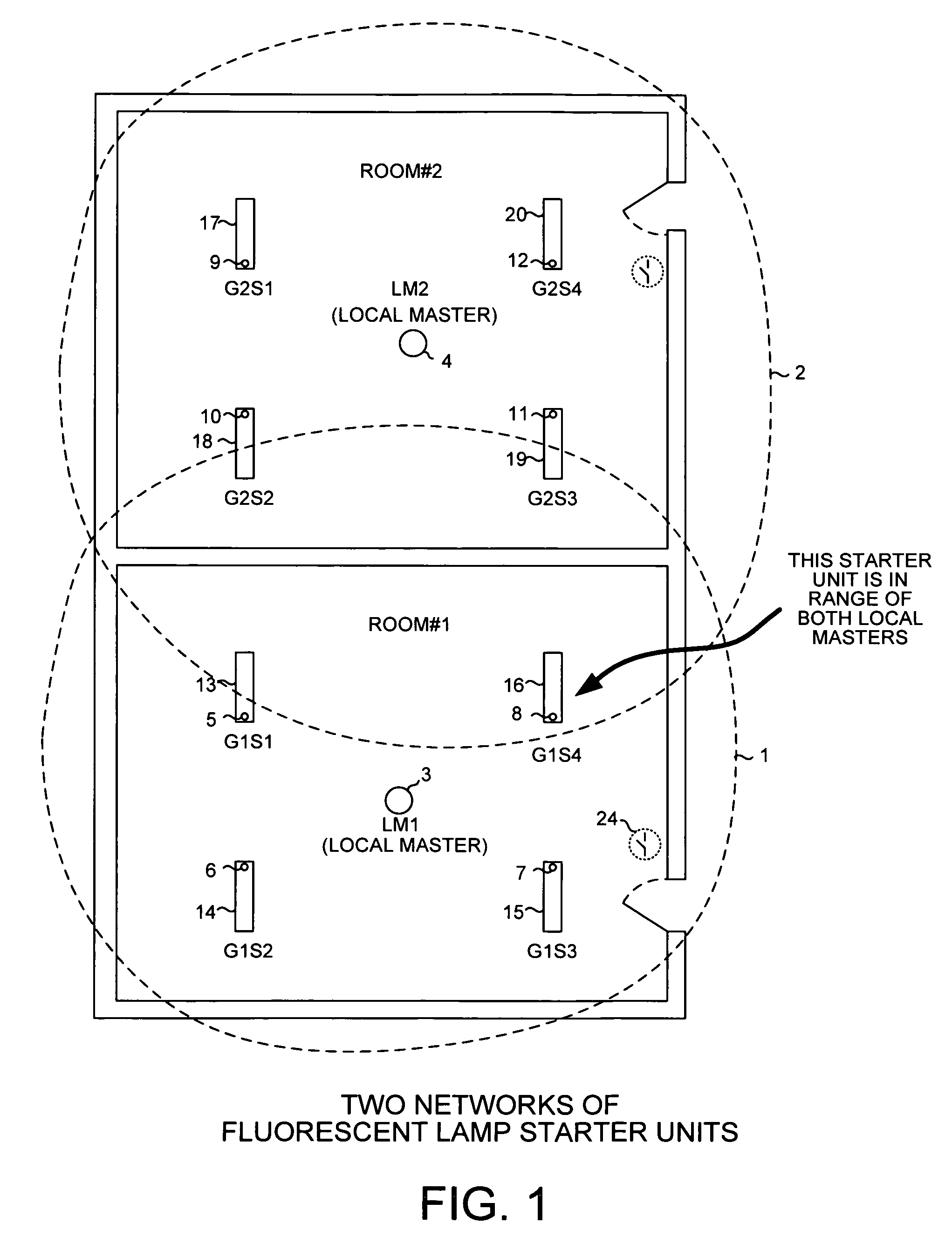
[0024]FIG. 1 is a diagram of two networks 1 and 2. Each network is a time-hopping wireless network involving a local master unit that is in Radio Frequency (RF) wireless communication with a plurality of remote lighting control units. Network 1 involves local master unit (LM1) 3 and four lighting control units (G1S1, G1S2, G1S3, G1S4) 5-8. Similarly, network 2 involves local master unit (LM2) 4 and four lighting control units (G2S1, G2S2, G2S3, G2S4) 9-12. In the illustrated example, each of the lighting control units is an RF-enabled replaceable fluorescent lamp starter unit that is plugged into an accommodating socket fluorescent lamp light fixture such that the starter unit can be controlled by its local master to turn on a lamp of the fixture and to turn off the lamp of the fixture. Starter unit 5 is plugged into ...


PUM


Abstract

A low-power wireless network involves a master and a plurality of RF-enabled fluorescent lamp starter units. In each of a plurality of intervals, a starter wakes up and listens for a beacon, regardless of whether a beacon is transmitted during that interval or not. The starter operates in a low power sleep mode during the majority of the interval. The master can transmit during the beacon slot time of any interval, but typically only transmits frequently enough to maintain starter synchronization. If the master wishes to communicate with the starters with reduced latency, then the master can transmit a beacon in the next interval. Beacon slot time is varied within the interval (for example, from interval to interval or from group of intervals to group of intervals) in a pseudo-random time-hopping fashion known to both the starters and the master, thereby reducing persistence of collisions with similar networks.

Description

TECHNICAL FIELD[0001]The described embodiments relate to low-power wireless networks, and more particularly to a low-power wireless network involving RF-enabled fluorescent lamp starter units that are controlled by a battery-powered occupancy detector.BACKGROUND INFORMATION[0002]Many wireless protocols and systems have been used or have been proposed for use in controlling lighting systems. Some of these protocols and systems include IEEE 802.11 Wi-Fi, Bluetooth, X10, Z-Wave, INSTEON, nanoNET and ZigBee. Each of these protocols has its advantages and disadvantages. In one proposed ZigBee-based lighting control system, a central device referred to as the coordinator communicates wirelessly with multiple endpoint devices in a star topology. Each endpoint device is a Reduced Function Device (RFD) that is embedded in a lighting fixture. The central coordinator, on the other hand, is a Full Function Device (FFD) that can be made to turn on and to turn off the lighting fixtures by sending...

Claims


Application Information

Patent Timeline
Patent Type & Authority Patents(United States)
IPC IPC(8): H04B1/00
CPCH04W52/0229G08C17/02H04W74/085H04W84/20H05B37/0272G08C2201/12Y02B60/50Y02D30/70H05B47/195
Inventor POPE, STEVEN M.
Owner IXYS INTL LTD
Why Eureka
Try Eureka