Rolling bearing with a rotation sensor

a technology of rotation sensor and rolling bearing, which is applied in the direction of instruments, mechanical devices, devices using electric/magnetic means, etc., can solve the problem of laborious mounting process, achieve the effect of preventing damage to the output cables of the magnetic sensor, facilitating the drawing of output cables outside the sensor housing, and facilitating the closur

Active Publication Date: 2012-05-29
NTN CORP
View PDF19 Cites 5 Cited by
  • Summary
  • Abstract
  • Description
  • Claims
  • Application Information

AI Technical Summary

Benefits of technology

[0005]An object of this invention is to protect the output cables of the magnetic sensor from damage and, at the same time, to facilitate the process of mounting the output cables to extend to the outside.
[0007]In this invention, the opening extending from the proximal end to the distal end of the tubular duct is provided on the side face of the tubular duct. The output cables are mounted through the duct via this opening, and then the lid is mounted to close the opening. Thus damage to the output cables of the magnetic sensor is prevented and, at the same time, drawing the output cables outside the sensor housing is made easier.
[0008]The opening of the duct can be closed more easily by configuring that the opening of the tubular duct has a uniform width from the proximal end to the distal end thereof so that the lid is to be mounted in the opening by sliding from the distal end to the proximal end thereof.
[0009]In the rolling bearing with a rotation sensor of this invention, the sensor housing is integrally formed with the tubular duct having an opening formed in the side face thereof to extend from its proximal to distal ends. The output cables are mounted through the duct by being inserted laterally via this opening, and then the lid is mounted to close the opening. Thus damage to the output cables of the magnetic sensor is prevented and, at the same time, drawing the output cables outside the sensor housing is made easier.
[0010]The opening of the duct can be closed more easily by making the opening of the duct extend with a uniform width from the proximal end to the distal end of the duct so that the lid is mounted in the opening by sliding it from the distal end to the proximal end thereof.

Problems solved by technology

But the output cables connected to the circuit board inside the sensor housing have to be mounted to extend outside through the tubular duct, and the mounting process is a laborious process.

Method used


Image

  • Rolling bearing with a rotation sensor
  • Rolling bearing with a rotation sensor
  • Rolling bearing with a rotation sensor

Examples


Embodiment Construction

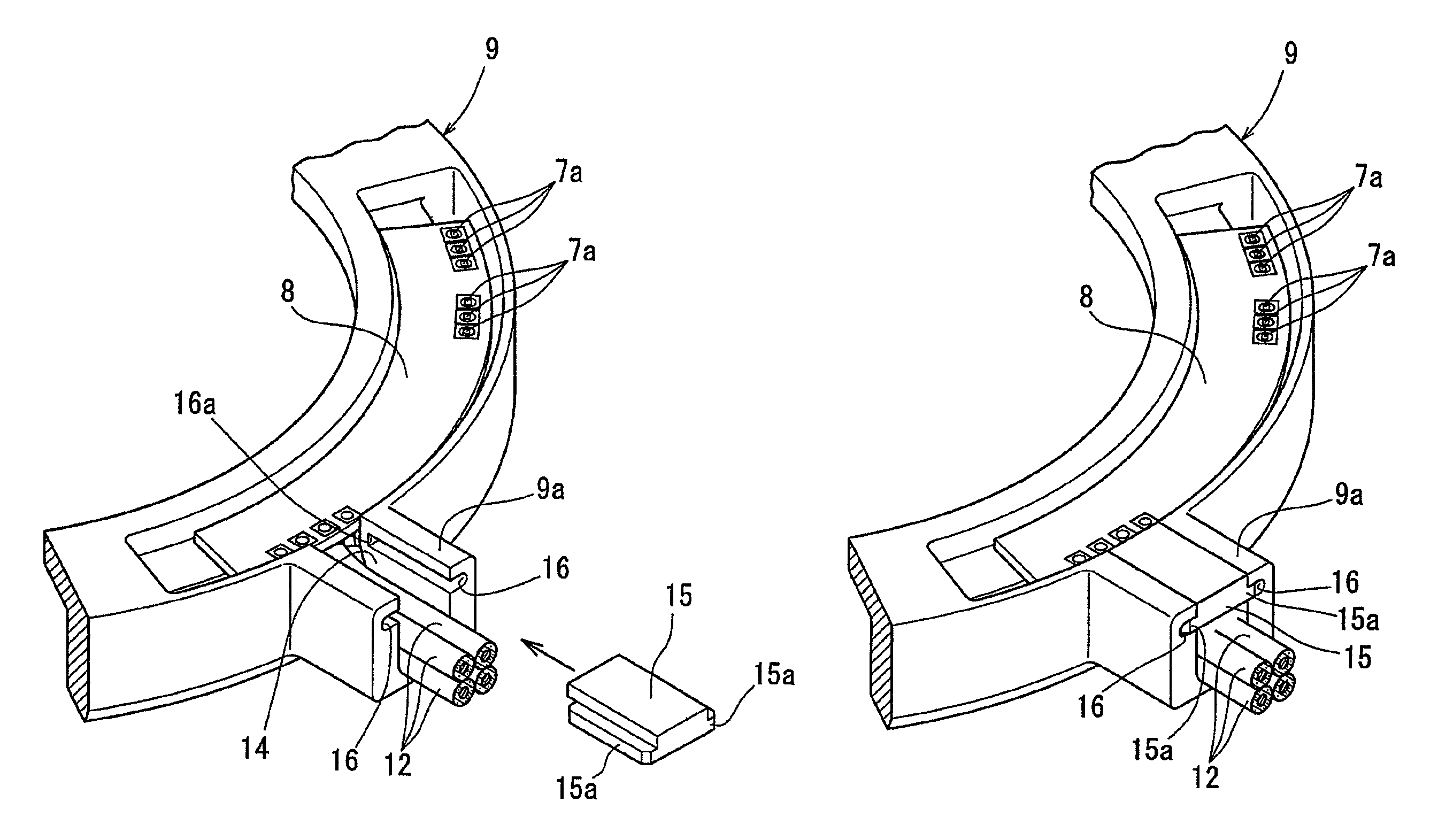
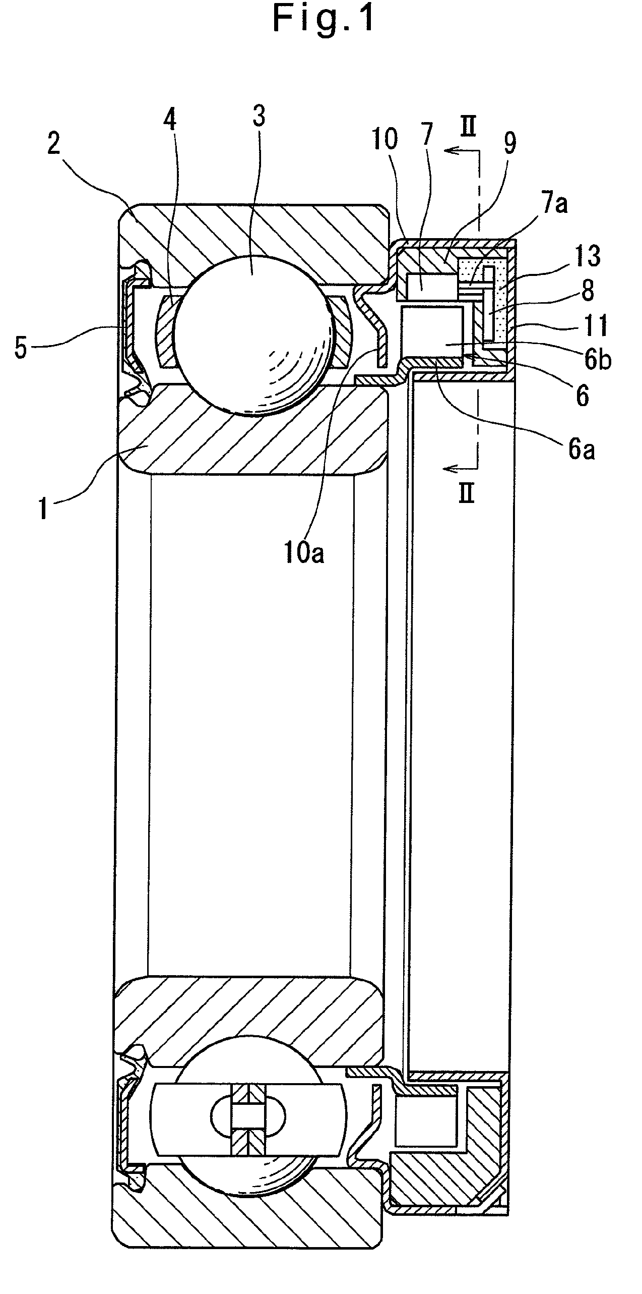
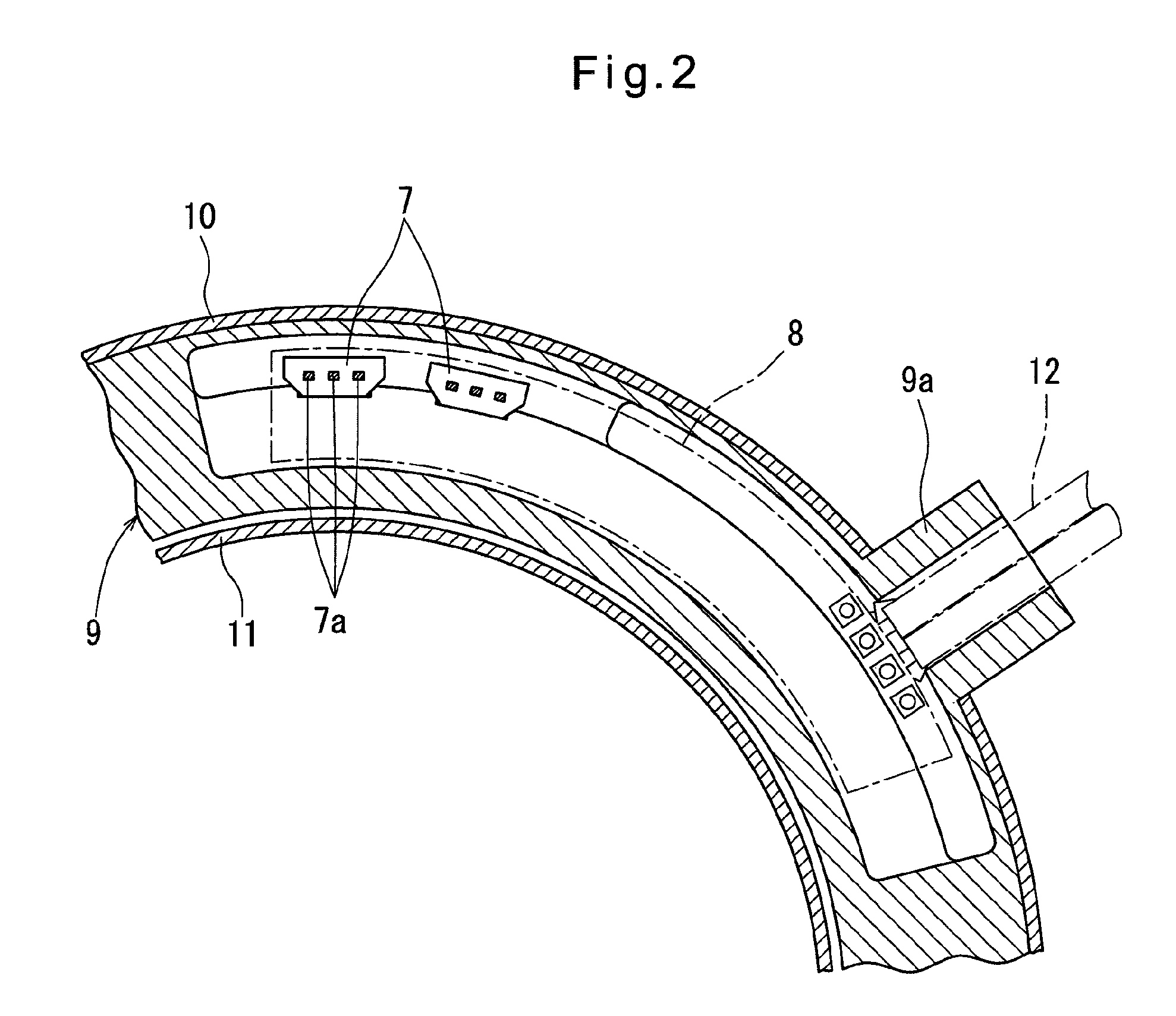
[0014]An embodiment of this invention is now described with reference to the drawings. As shown in FIG. 1, the rolling bearing with a rotation sensor of the embodiment is a deep groove ball bearing comprising an inner race 1, which is rotatable, an outer race 2, which is stationary, and balls 3 provided between the inner and outer races and retained by a retainer 4. A magnetic encoder 6 is mounted on one side of the inner race 1, and a sensor housing 9, receiving magnetic sensors 7 and a circuit board 8, is mounted on the one side of the outer race 2 facing the magnetic encoder 6. On the other side of the outer race 2, which is axially opposite to the sensor housing 9, a seal member 5 is mounted to seal the interior of the bearing.

[0015]The magnetic encoder 6 comprises an annular core 6a and a magnetic body 6b polarized alternately in different magnetic poles in the circumferential direction, the core 6a being fitted around the inner race 1.

[0016]The sensor housing 9 is made of a po...


PUM


Abstract

In a magnetic sensor 7, a tubular duct 9a for output cables 12 is formed integrally with a sensor housing 9, provided with an opening 14 having a uniform width from a proximal end to a distal end of the duct 9a on a side face thereof. The output cables 12 are mounted through the duct 9a from this opening 14, and then a slidable lid 15 is mounted to close the opening 14. Thus damage to the output cables 12 connected to the magnetic sensor 7 is prevented and, at the same time, drawing the output cables 12 outside the sensor housing 9 is made easier.

Description

TECHNICAL FIELD[0001]This invention relates to a rolling bearing with a rotation sensor.BACKGROUND OF THE INVENTION[0002]A rolling bearing with a rotation sensor is sometimes used for supporting a rotation shaft in a variety of devices to detect its rotational speed (number of revolutions). This rolling bearing with a rotation sensor has an annular magnetic encoder alternately polarized in different magnetic poles in the circumferential direction and mounted on one of the inner and outer races of the bearing that is rotatable. A sensor housing incorporating a magnetic sensor for detecting the change of the magnetic flux when the encoder rotates is mounted on the other stationary race to detect the rotation of the rotating race. A circuit board for processing the output of the magnetic sensor is often mounted in the sensor housing.[0003]In many cases, such a sensor housing for a rolling bearing with a rotation sensor is made of a resin, and mounted on the stationary race through a me...

Claims


Application Information

Patent Timeline
Patent Type & Authority Patents(United States)
IPC IPC(8): G01B7/30
CPCF16C33/80G01D5/145G01D11/245G01P1/026G01P3/443F16C41/007F16C19/06F16C33/7886
Inventor ITO, HIROYOSHI
Owner NTN CORP
Why Eureka
Try Eureka