Computer generated hologram, exposure apparatus and device fabrication method

a technology of exposure apparatus and hologram, which is applied in the direction of hologram nature/properties, printing, instruments, etc., can solve the problems of reducing the transmittance of general glass materials, difficult to further shorten the current exposure light wavelength, and difficulty in further increasing the na of the projection optical system available, so as to reduce the illuminance variation and light loss, and the structure is thin.

Inactive Publication Date: 2012-05-29
CANON KK
View PDF8 Cites 5 Cited by
  • Summary
  • Abstract
  • Description
  • Claims
  • Application Information

AI Technical Summary

Benefits of technology

[0020]The present invention provides a computer generated hologram which can suppress an illuminance variation and a loss in light amount and achieve a structure thinner than ever, thus forming a light intensity distribution (reproduced image) with a desired shape and polarization state.

Problems solved by technology

However, it is difficult to further shorten the current exposure light wavelength because the transmittance of a general glass material decreases as the exposure light wavelength shortens.
It is also difficult to further increase the NA of the projection optical system available at present because the depth of focus decreases in inverse proportion to the second power of the NA of the projection optical system, and because it is hard to design and manufacture lenses to form a high-NA projection optical system.
However, the prior arts form sub-CGHs by dividing one CGH into a plurality of CGHs, so an illuminance variation occurs in the reproduced image if the optical integrator cannot sufficiently correct the intensity distribution of the incident light (for example, if the light impinges on only some of these CGHs).
When a plurality of sub-CGHs are combined, unnecessary diffracted light is generated due to structural discontinuity that occurs at the boundary between the sub-CGHs, resulting in deterioration in the reproduced image obtained by the CGH.
The structural discontinuity that occurs at the boundary between the sub-CGHs can be eliminated by improving the design of a computer generated hologram, but this poses another problem that the design cost increases enormously.
For this reason, the achievement of thinner elements is a challenge always encountered in designing and manufacturing CGHs.

Method used


Image

  • Computer generated hologram, exposure apparatus and device fabrication method
  • Computer generated hologram, exposure apparatus and device fabrication method
  • Computer generated hologram, exposure apparatus and device fabrication method

Examples


first embodiment

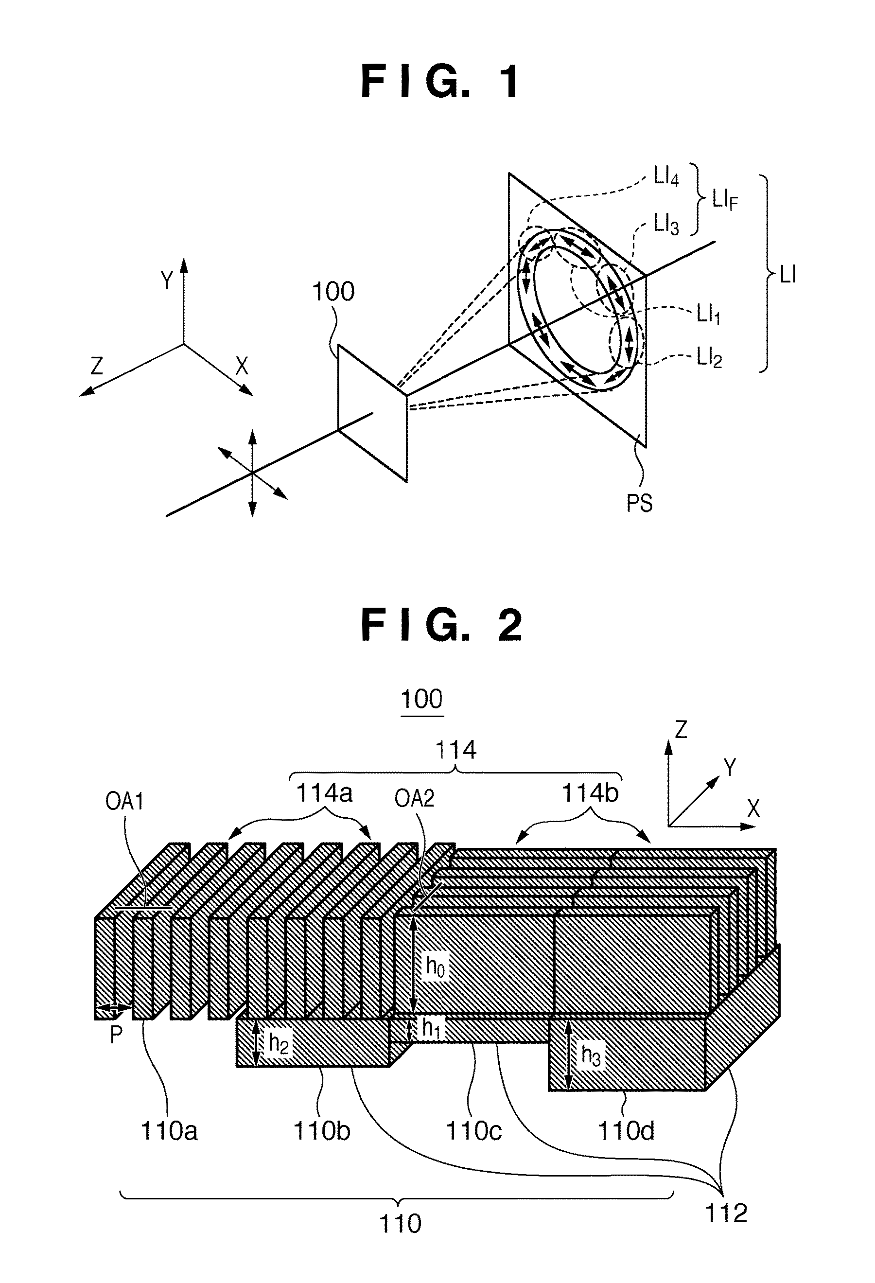
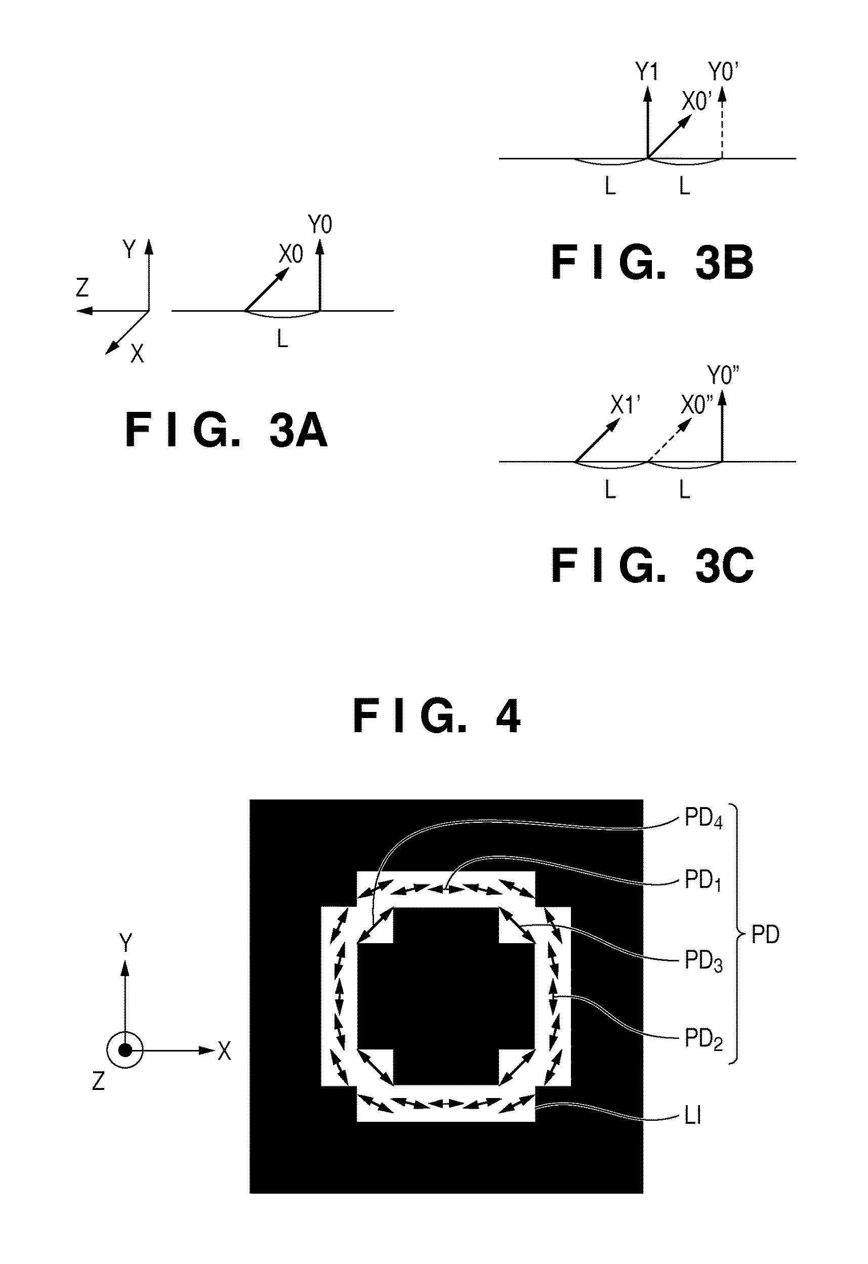
[0073]A design example of a computer generated hologram which forms a phase distribution including two phases assuming an annular light intensity distribution formed by S-polarized light as a target image will be explained in the first embodiment. More specifically, a case in which a computer generated hologram 100 forms an annular light intensity distribution (target image) LI as shown in FIG. 4 will be explained. FIG. 4 is a view showing an example of an annular light intensity distribution (target image) LI formed by the computer generated hologram 100.

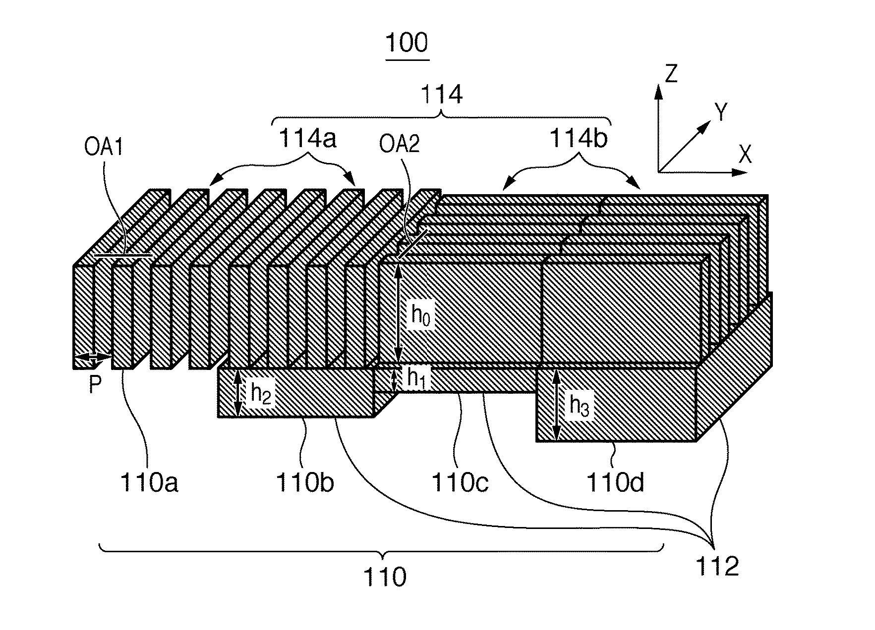
[0074]Polarization directions PD in the light intensity distribution LI shown in FIG. 4 include a plurality of polarization directions PD1 to PD4, and are parallel to the circumferential direction of concentric circles (i.e., correspond to S-polarization). How to design a computer generated hologram 100 which forms a light intensity distribution LI as shown in FIG. 4 will be explained using cells 110a to 110d shown in FIG. 2.

[0075]...

second embodiment

[0085]A design example of a computer generated hologram which forms a phase distribution including four phases assuming an annular light intensity distribution formed by S-polarized light as a target image will be explained in the second embodiment. More specifically, a case in which a computer generated hologram 100 forms an annular light intensity distribution (target image) LI as shown in FIG. 4 will be explained, as in the first embodiment.

[0086]FIG. 9A is a chart showing the phase distribution of a computer generated hologram designed by DBS to be compatible with the intensity and phase of the X-polarized light component shown in FIGS. 5A and 6A, respectively. FIG. 9B is a chart showing the phase distribution of a computer generated hologram designed by DBS to be compatible with the intensity and phase of the Y-polarized light component shown in FIGS. 5B and 6B, respectively. The phase distributions of the computer generated hologram shown in FIGS. 7A and 7B are represented by ...

third embodiment

[0117]In the third embodiment, an exposure apparatus 1 to which the computer generated hologram 100 according to the present invention is applied will be explained below with reference to FIG. 13. FIG. 13 is a view showing the arrangement of the exposure apparatus 1 according to one aspect of the present invention.

[0118]In this embodiment, the exposure apparatus 1 is a projection exposure apparatus which transfers the pattern of a reticle 20 onto a wafer 40 by the step & scan scheme. However, the exposure apparatus 1 can adopt the step & repeat scheme or another exposure scheme.

[0119]As shown in FIG. 13, the exposure apparatus 1 includes an illumination apparatus 10, a reticle stage (not shown) for supporting the reticle 20, a projection optical system 30, and a wafer stage (not shown) for supporting the wafer 40.

[0120]The illumination apparatus 10 illuminates the reticle 20 on which a circuit pattern to be transferred is formed, and includes a light source 16 and illumination optic...


PUM


Abstract

A computer generated hologram includes a plurality of cells which form a light intensity distribution on a predetermined plane. The plurality of cells includes a plurality of first cells including isotropic media and anisotropic media, and a plurality of second cells including anisotropic media alone. The plurality of cells change a phase of incident light which impinges on each of the plurality of cells to form a phase distribution including N phases (N is the number of phases, N≧2) for each of a wavefront of a linearly polarized light component in a first direction and a wavefront of a linearly polarized light component in a second direction perpendicular to the first direction.

Description

BACKGROUND OF THE INVENTION[0001]1. Field of the Invention[0002]The present invention relates to a computer generated hologram, an exposure apparatus and a device fabrication method.[0003]2. Description of the Related Art[0004]A projection exposure apparatus has conventionally been employed to fabricate a micropatterned semiconductor device such as a semiconductor memory or logic circuit by using photolithography. The projection exposure apparatus projects and transfers a circuit pattern formed on a reticle (mask) onto a substrate such as a wafer via a projection optical system.[0005]The resolution R of the projection exposure apparatus is given by:[0006]R=k1×λNA(1)[0007]where λ is the exposure light wavelength, NA is the numerical aperture of the projection optical system, and k1 is a process constant determined by, e.g., a development process.[0008]The shorter the exposure light wavelength or the higher the NA of the projection optical system, the better the resolution. However, i...

Claims


Application Information

Patent Timeline
Patent Type & Authority Patents(United States)
IPC IPC(8): G03H1/02G03H1/08G03H1/04
CPCG03F7/70108G03F7/70566G03H1/08G03H1/0891G03H2001/0212G03H2001/2276G03H2222/31G03H2223/20G03H2240/13G03H2240/15G03H2240/55G03H2260/51G03H2240/41G03F7/70075G03F7/70308
Inventor MATSUBARA, ISAO
Owner CANON KK
Why Eureka
Try Eureka