Building integrated solar array support structure device, system, and method

a solar array and support structure technology, applied in the field of building integrated solar array support structure devices, systems and methods, can solve the problems of deterioration of the physical and electrical properties of solar arrays, significant reduction of the efficiency of solar arrays, and state of the art mounting systems and structures and methods that have not provided an effective, cost-effective solution, and achieve the effect of economic installation

Active Publication Date: 2012-06-05
ENERGY DESIGN
View PDF12 Cites 49 Cited by
  • Summary
  • Abstract
  • Description
  • Claims
  • Application Information

AI Technical Summary

Benefits of technology

[0011]The various preferred embodiments of the present invention provide a device, system and method for mounting solar panels in an array that overcomes the limitations of the current art. Specifically, the various preferred embodiments of the present invention provide an integrated photovoltaic mounting system, device, and method of use that serves a dual purpose of a mounting structure for a solar electric system and also serving as a water shedding roof with a system designed to channel water to desired locations, such as an existing roof-gutter system provided by the structure. Moreover, the present invention includes structural elements that channel water in both a longitudinal (north-south) direction and a latitudinal (east-west) direction. Further, the various preferred embodiments are economical to install and provide all amenities customarily provided by known mounting structures prevalent in this art.
[0018]In another preferred embodiment of the invention uses a slotted top cap in place of the east-west water gutter secured from under the solar module's bottom frame edge with a stainless steel self threading screw that goes through a bottom plate, or a stainless steel fender washer, and threads into a slot in the slotted top cap. The slotted top cap has an attached gasket that serves to seal the east-west gap between the solar modules.

Problems solved by technology

Further, as the arrays are necessarily exposed to the elements, they are subject to all weather conditions imaginable.
Precipitation is a leading cause of deterioration of the physical and electrical properties of solar arrays.
Moisture from rain or melting snow, for example, can lead to delaminating or electrical failure of the individual solar modules and significantly reduce the efficiency of the array.
However, the current state of the art of mounting systems and structures and methods has yet to provide an effective, cost-efficient solution that provides a stable structure, pathways for electrical components, acceptable means for ridding moisture from the array, and diverting that moisture to desired locations.
But, Poddany, does not contemplate, disclose, instruct, or imply any structure suited to direct the water once it is off the photovoltaic panel, or to intentionally channel water once it reaches the frame bracket, nor to direct water within the frame bracket, and further provides no structure or teaching to direct water from each individual panel when linked together to form an array of panels including no instruction on how to move water in both in a lateral and longitudinal direction to a desired position.
Further, the Poddany apparatus, also, does not instruct, contemplate, or disclose any structural elements or methods to provide a continuous, moisture-proof system of panels and brackets that would be well-suited to act as a roof structure that would keep the area below the system dry.
Other known solar panel mounting systems not only fail to provide structure suitable for intentionally diverting rain water, but provide less-than-ideal amount of panel surface on both the top and bottom sides of the modules in the array.
Necessarily, the conduits for electrical raceways and for concealing electrical components are ill suited to direct or channel water.

Method used


Image

  • Building integrated solar array support structure device, system, and method
  • Building integrated solar array support structure device, system, and method
  • Building integrated solar array support structure device, system, and method

Examples


Embodiment Construction

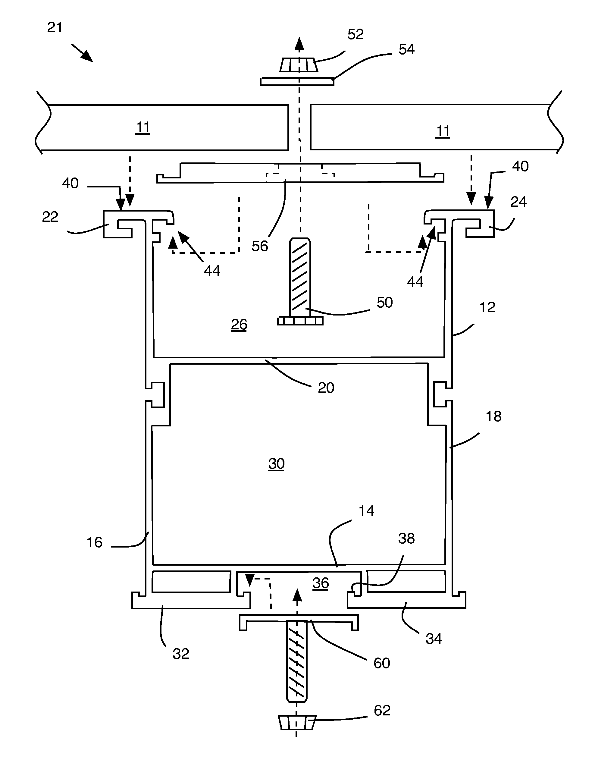
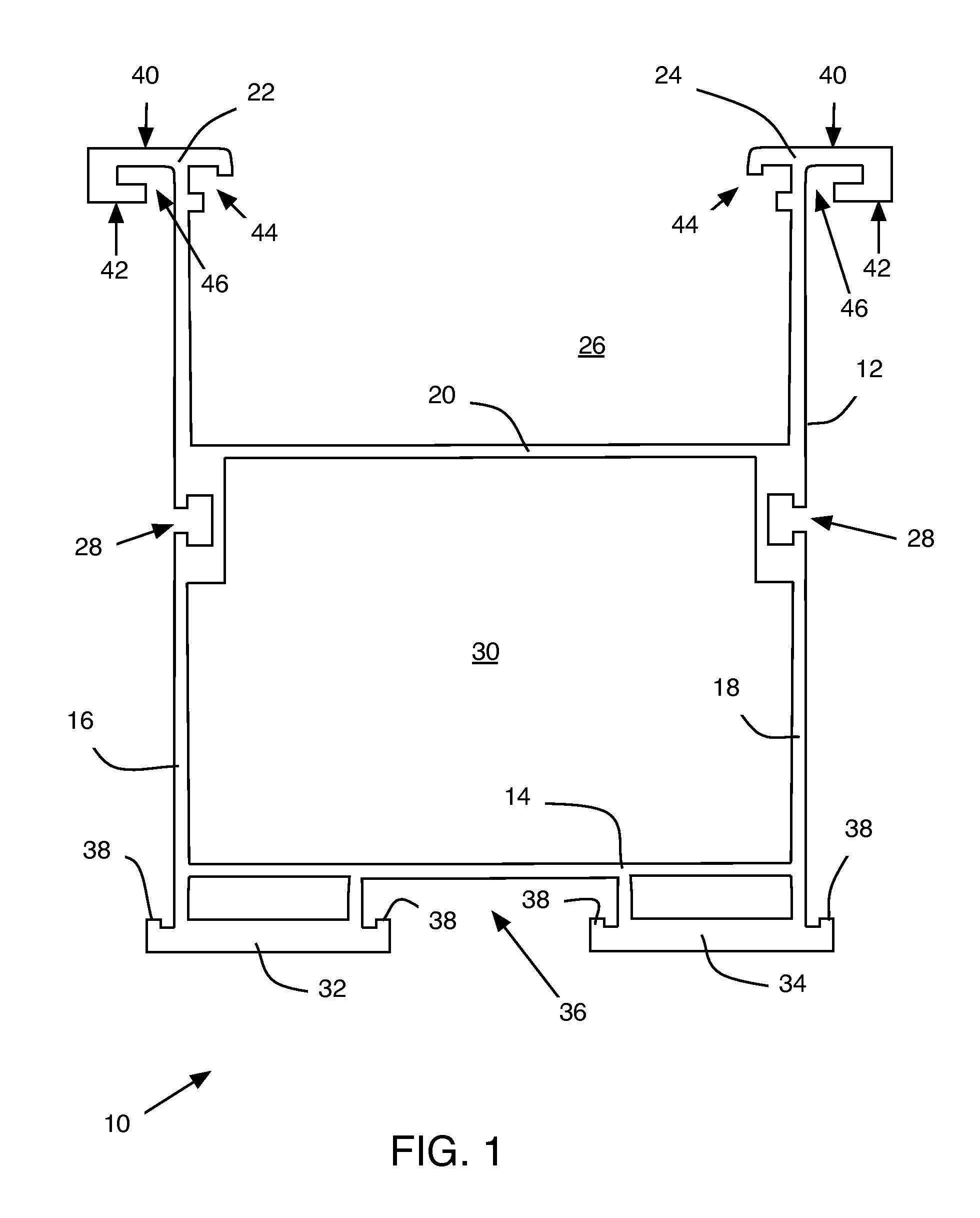
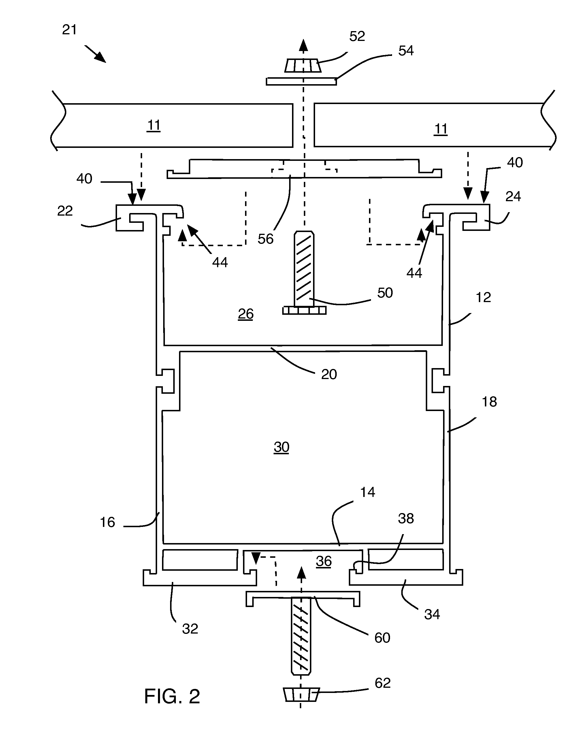
[0061]Possible preferred embodiments will now be described with reference to the drawings and those skilled in the art will understand that alternative configurations and combinations of components may be substituted without subtracting from the invention. Also, in some figures certain components are omitted to more clearly illustrate the invention.

[0062]With general reference to all the figures of the drawing, the various preferred embodiments of the present invention contemplate supporting, coupling, and otherwise interfacing with common solar modules. Commonly, almost all solar modules all have an aluminum frame all the way around the module. The glass and solar cells are actually only a ⅛″ thick or so but the aluminum frame around it is usually a 1″ deep or so all the way around (a module with aluminum frame is shaped exactly like a box lid that can slide down onto a box).

[0063]Accordingly, the present invention includes both north-south structural members and east-west weatheri...


PUM


Abstract

The system provides an n-s rail bracket that both supports a plurality of solar panels structurally, provides view-guards to hide electrical components, and a water conduit to channel water shed from the solar panel to a desired collection point provided by the structure. As such, the system includes an n-s structural rail consisting of a bottom wall and two vertically extending sidewalls. An intermediate horizontal member extends between the two sidewalls at or near their midpoint to form a compartment between the intermediate horizontal member, a lower portion of the left sidewall, the bottom wall, and a lower portion of the right side wall. Also, the intermediate horizontal member cooperates with an upper portion of the left side wall and an upper portion of the right sidewall to form a U-shaped channel. Each distal end of the respective left and right side wall includes a T-shaped shoulder for supporting the solar module.

Description

BACKGROUND[0001]This invention relates to a device and system directed to a mounting structure for solar collectors and more specifically to a system that both mounts solar collectors to a structure and directs water off the solar collectors and structure.[0002]Photovoltaic modules (solar collectors), typically arranged as an array of rows and columns of individual solar modules, receive light to generate electricity. Modern solar arrays increase efficiency significantly when arranged to receive both direct sunlight (top surface) and ambient reflected light (top and bottom surfaces). Therefore, there is a recent effort to improve the mounting systems to suspend an array in such a way as to maximize the surface area of both the top and bottom sides of each solar module.[0003]Further, as the arrays are necessarily exposed to the elements, they are subject to all weather conditions imaginable. Precipitation is a leading cause of deterioration of the physical and electrical properties o...

Claims


Application Information

Patent Timeline
Patent Type & Authority Patents(United States)
IPC IPC(8): E04H14/00E04D13/18
CPCE04D13/0445F24J2/4614F24J2/5207F24J2/5258H02S20/23F24J2002/5215F24J2002/5296Y02B10/12Y02B10/20Y02E10/47F24J2002/5226F24S25/35F24S25/636F24S40/44F24S2025/022F24S2025/801F24S2025/807Y02B10/10Y02E10/50
Inventor MCCLELLAN, VNCENT JACKMORRISON, ERIC ROYHELLER, RY REUTER
Owner ENERGY DESIGN
Why Eureka
Try Eureka