

Transom reinforcement grid
a transom and reinforcement technology, applied in the field of reinforcement grids, can solve the problems of inability to terminate longitudinal stringers in the reinforcement grid, undesirable deflection, stress, fatigue of laminates, etc., and achieve the effect of improving the rigidity of the transom
- Summary
- Abstract
- Description
- Claims
- Application Information
AI Technical Summary
Benefits of technology
Problems solved by technology
Method used
Image

Examples
Embodiment Construction
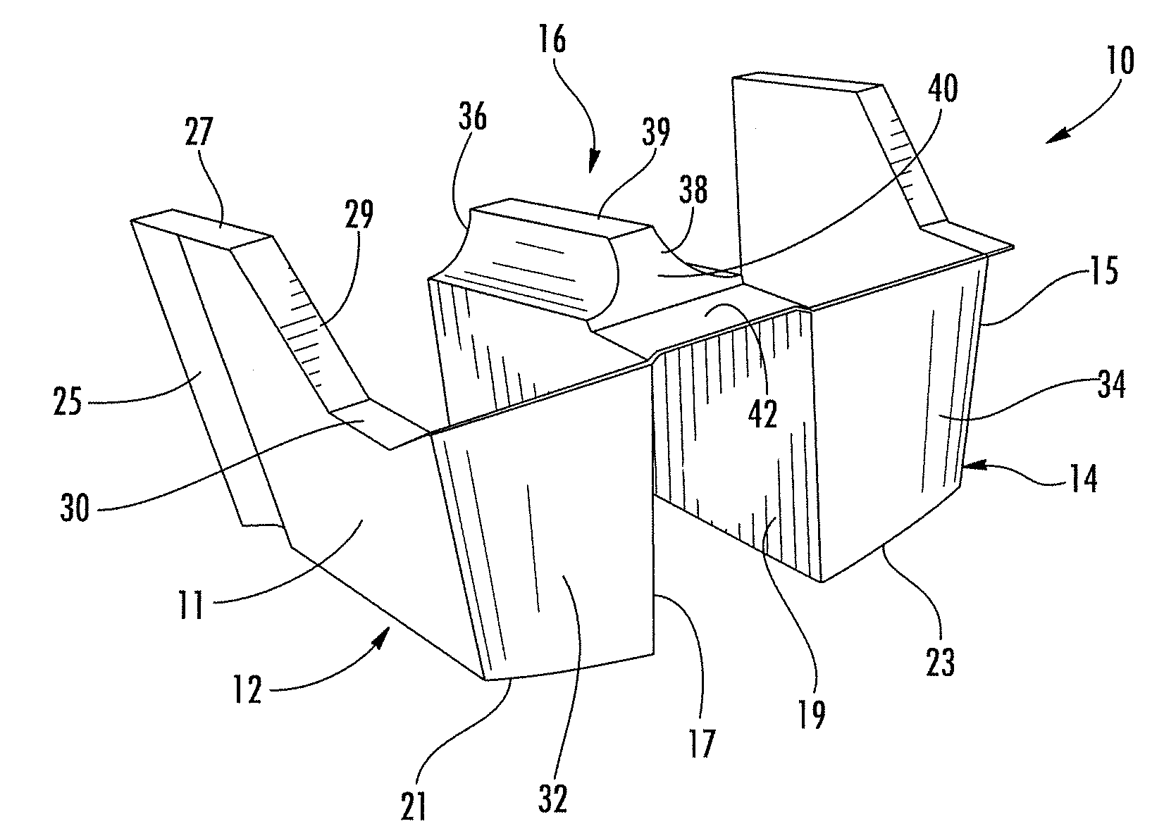
[0020]As used herein, the term “longitudinally”, with respect to the direction of orientation of the grid in a vessel, pertains to the fore and aft direction of the vessel; “transversely,”“outwardly” or “laterally”, as used herein, refers to port to starboard directions of the vessel, while “vertically extending” has its normal bottom-to-top meaning. Vessel and boat may be used interchangeably to refer generally to a pleasure boat or yacht made of a resinous or other material.
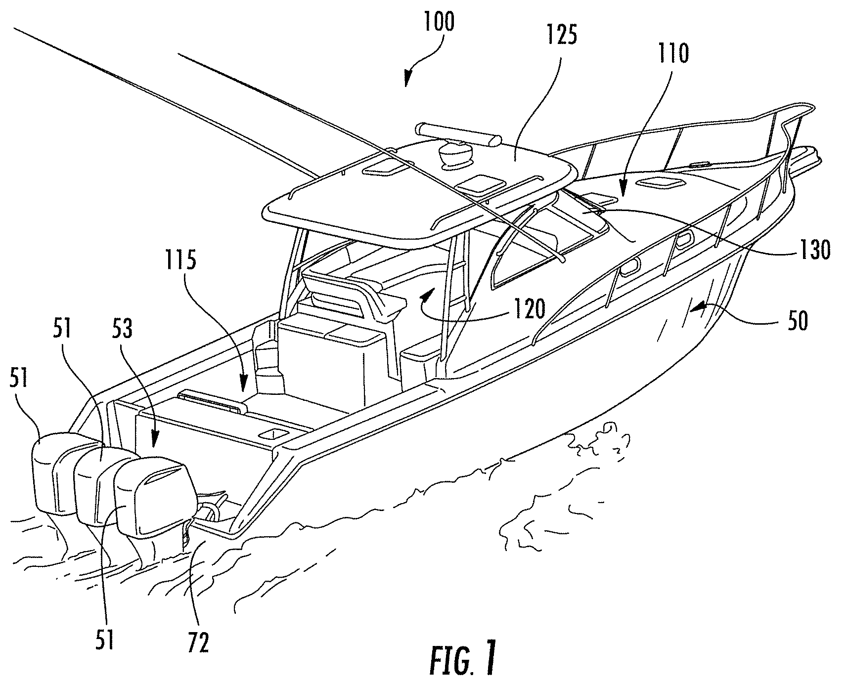
[0021]Referring initially to FIG. 1, there is shown an open style boat or vessel 100 which has a hull 50 and topside 110 which encloses the cabin and living area below. The vessel also includes a cockpit area 115 and bridge deck 120 enclosed by a hardtop 125 and windshield 130. The hull 50 extends aft to a motor well area 53 and transom 72. The vessel 100 is a high performance fishing boat that is powered by three 350 HP outboard engines 51 and has the improved structure for reinforcing the transom area of the ...
PUM
| Property | Measurement | Unit |
|---|---|---|
| thickness | aaaaa | aaaaa |
| thickness | aaaaa | aaaaa |
| length | aaaaa | aaaaa |
Abstract
Description
Claims
Application Information