Electrical connector

Active Publication Date: 2012-06-05
LOTES
View PDF5 Cites 34 Cited by
  • Summary
  • Abstract
  • Description
  • Claims
  • Application Information

AI Technical Summary

Benefits of technology

[0008]In one aspect, the present invention is directed to an electrical connector, which can preven

Problems solved by technology

However, the above method incurs the following problems.
Therefore, the recessed portion disposed on the bottom surface of the insulating body is displaced relative to the circuit board, and accordingly the grounding sheet accommodated in the recessed portion and the solder ball disposed corresponding to the ground

Method used


Image

  • Electrical connector
  • Electrical connector
  • Electrical connector

Examples


Example

LIST OF REFERENCE NUMERALS IN FIGS. 1-6

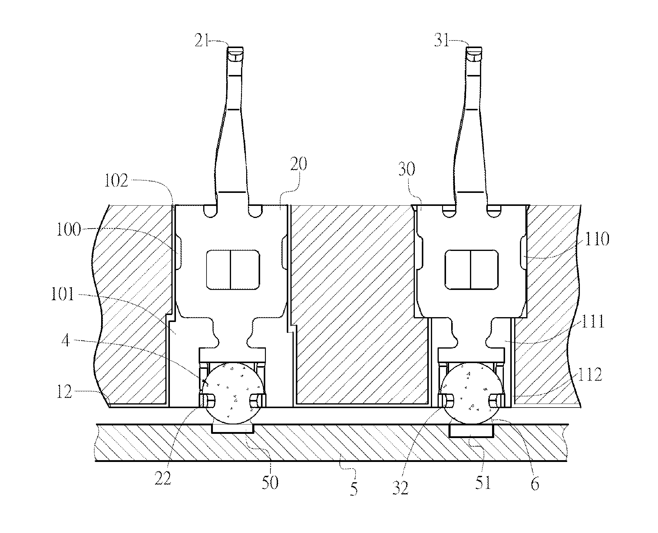
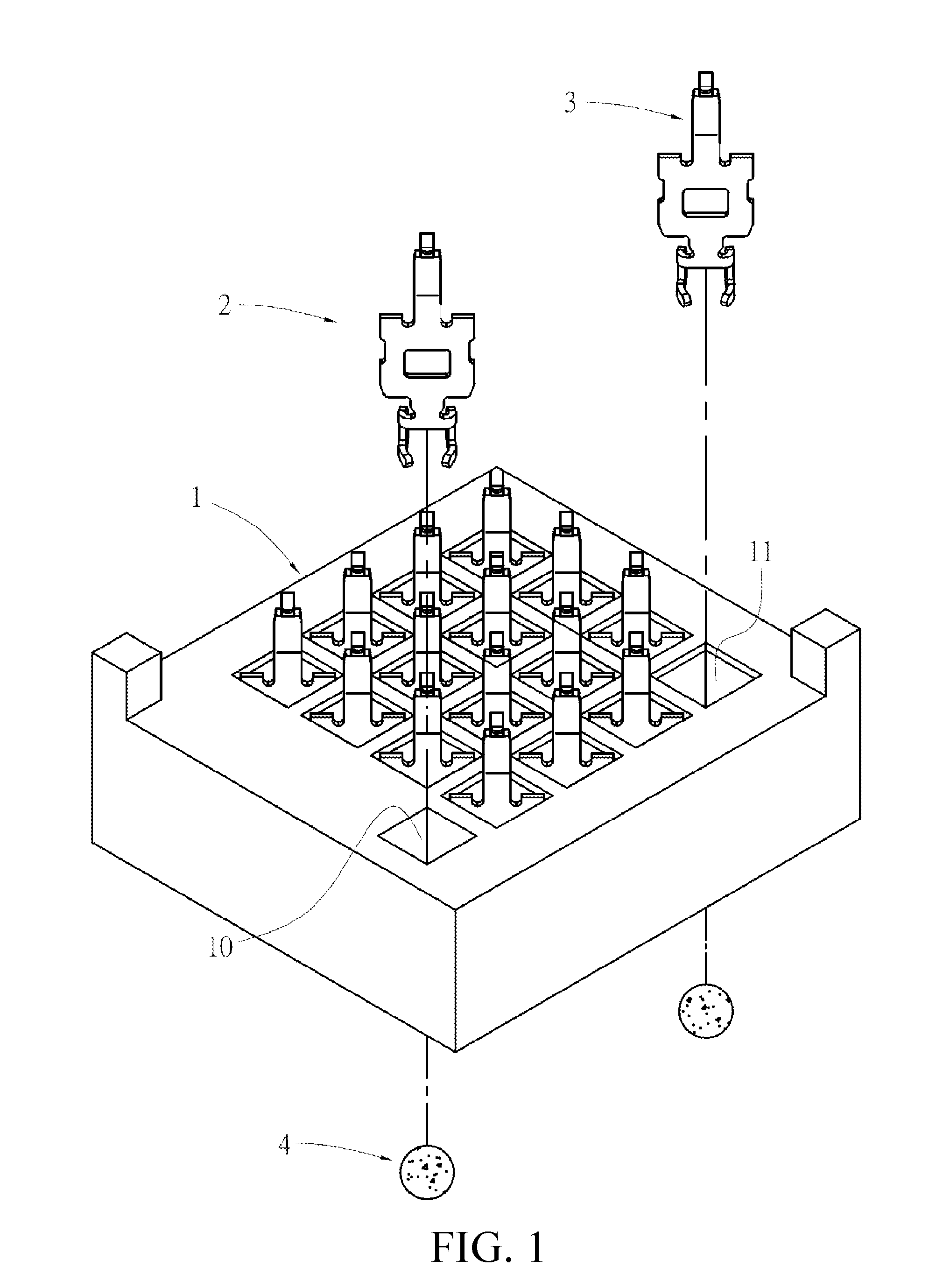
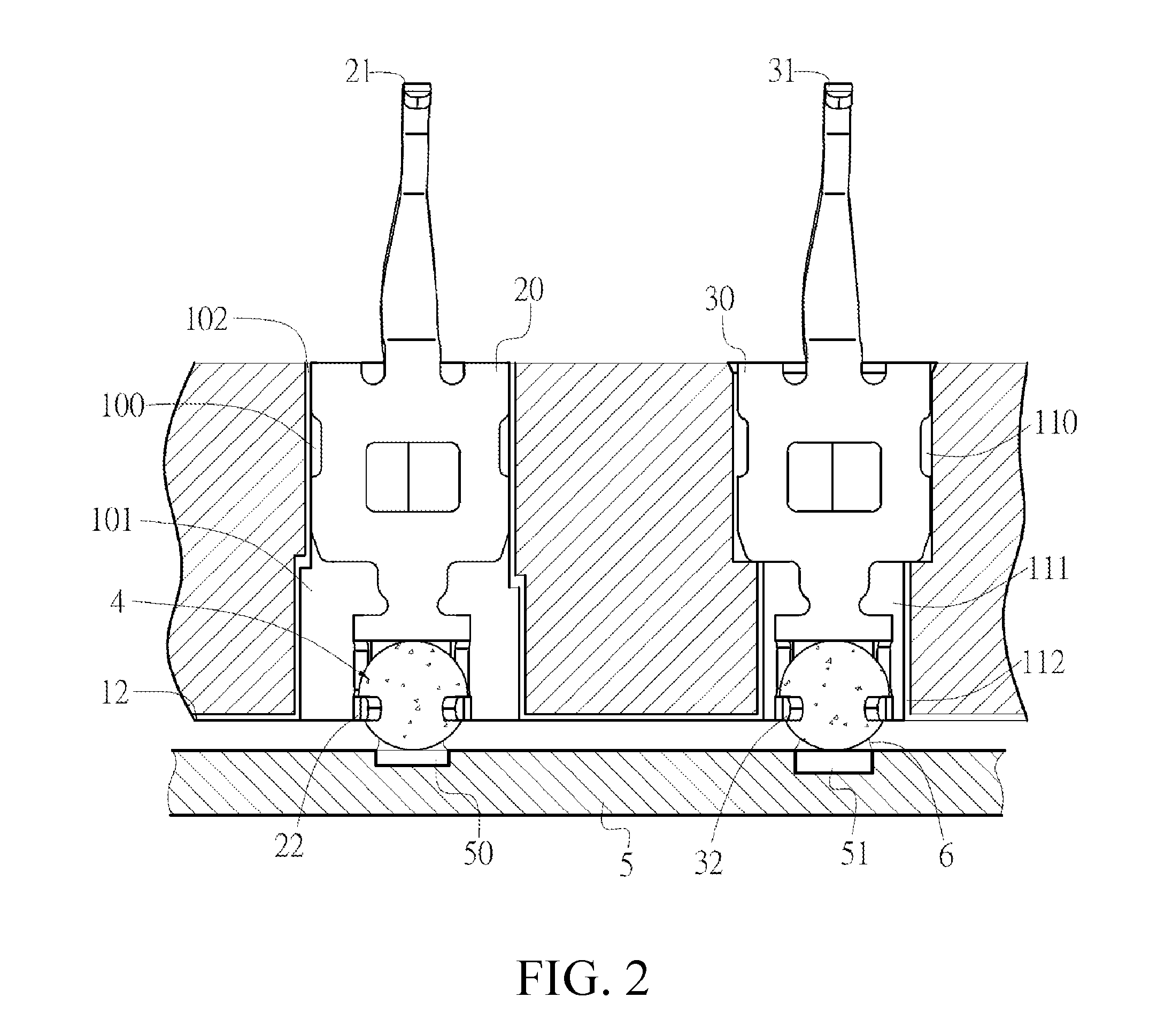
[0019]Insulating body1Grounding 10First retaining 100terminal slotslotFirst reserved 101First metal 102Signal terminal 11slotlayerslotSecond retaining110Second reserved 111Second metal 112slotslot layerThird metal layer12Grounding 2First base20First contact 21terminalportionFirst soldering 22First connecting220First clamping 221portionportionarmFirst clamping 222spaceSignal terminal3Second base30Second contact 31portionSecond soldering32Second connecting320Second clamping 321portionportionarmSecond clamping 322spaceSolder ball4Circuit board5First solder joint50Second solder 51Solder paste6joint

DETAILED DESCRIPTION OF THE INVENTION

[0020]The present invention is more particularly described in the following examples that are intended as illustrative only since numerous modifications and variations therein will be apparent to those skilled in the art. Various embodiments of the invention are now described in detail. Referring to the drawings, like ...


PUM


Abstract

An electrical connector for electrically connecting to a circuit board. In one embodiment, the electrical connector includes: an insulating body, having at least one grounding terminal slot and a plurality of signal terminal slots, at least one grounding terminal, made of a flexible conductive material and accommodated in the grounding terminal slot, and including a first base and a first soldering portion accommodated in the grounding terminal slot in a suspended manner, a plurality of signal terminals, and a plurality of solder balls, at least one of which is disposed on the first soldering portion.

Description

CROSS-REFERENCE TO RELATED APPLICATION[0001]This non-provisional application claims priority under 35 U.S.C. §119(a) on Patent Application No. 201120023079.1 filed in China on Jan. 24, 2011, the entire contents of which are hereby incorporated by reference.FIELD OF THE INVENTION[0002]The present invention relates to an electrical connector, and more particularly to an electrical connector for electrically connecting a chip module to a circuit board.BACKGROUND OF THE INVENTION[0003]Currently, an electrical connector for electrically connecting a chip module to a circuit board in the prior art includes an insulating body, a plurality of signal terminal slots formed through the insulating body, wherein a shielding layer is disposed in the signal terminal slot, a recessed portion is disposed at a bottom surface of the insulating body, and the recessed portion has a metal layer electrically conducted with the shielding layer, a plurality of signal terminals, respectively accommodated in ...

Claims


Application Information

Patent Timeline
IPC IPC(8): H01R12/00
CPCH01R12/57H01R12/714H05K3/3426H05K2201/10189H05K2201/10318H05K2201/10424Y02P70/50
Inventor JU, TED
Owner LOTES
Why Eureka
Try Eureka